Review
. 2019 Jan;7(1):e13862.
doi: 10.14814/phy2.13862.

Pacemaking in cardiac tissue. From IK2 to a coupled-clock system

Affiliations
Review

Pacemaking in cardiac tissue. From IK2 to a coupled-clock system

Edward Carmeliet. Physiol Rep. 2019 Jan.

Abstract

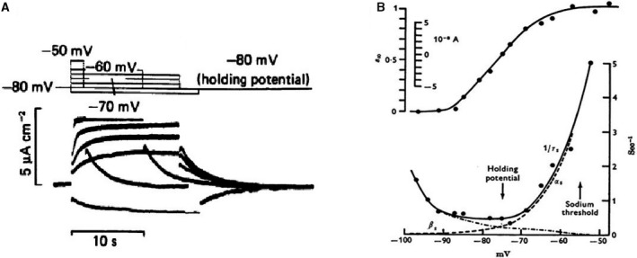
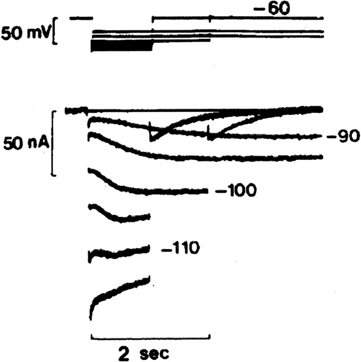
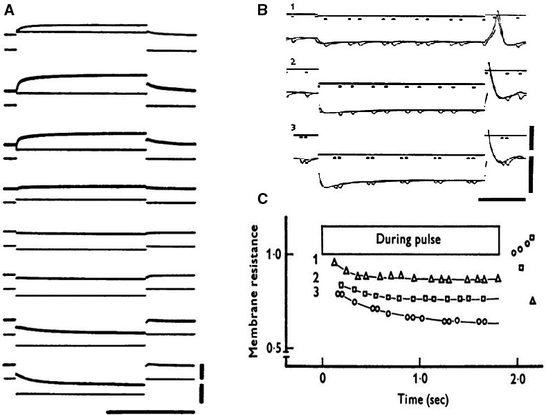
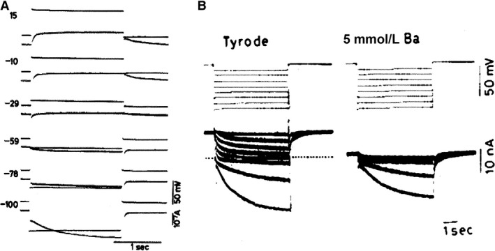
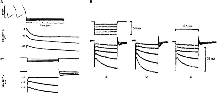
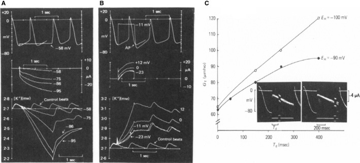
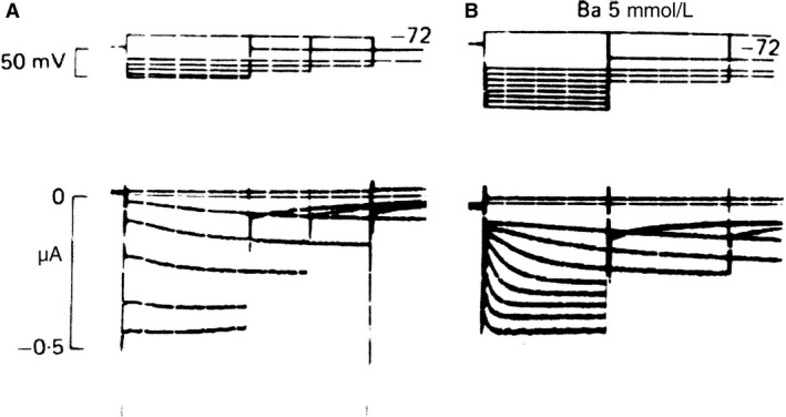
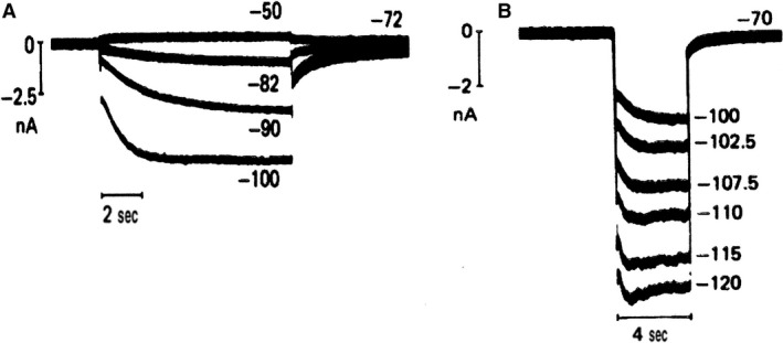
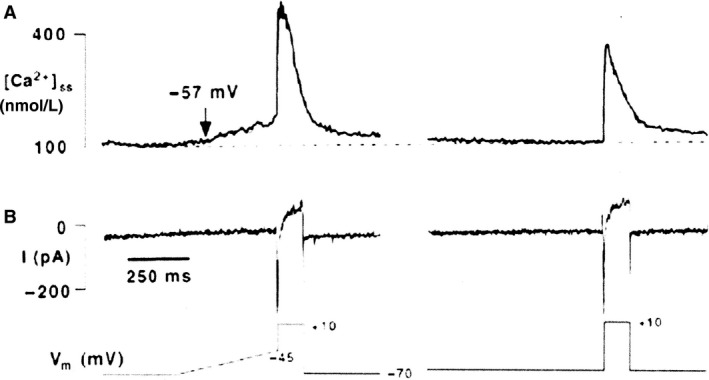
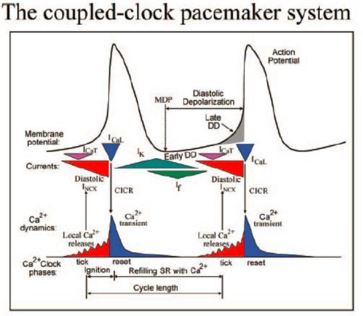
Initially, diastolic depolarization in Purkinje fibers was explained by deactivation of gK2 in the presence of inward current. Weakness of the hypothesis was a too negative reversal potential, sensitivity to external Na+ ions, existence of K+ depletion, and fake current during hyperpolarizing clamps. The development of a sinus node preparation of almost microscopic dimensions allowing uniform voltage clamps created new possibilities. Three different groups discovered in this improved node preparation an hyperpolarization induced time-dependent inward current, with a reversal potential positive to the resting potential, carried by a mixture of Na+ and K+ ions. A new current, If, or funny current was born. It is not the only pacemaker current. The following sequence of currents (membrane clock) has been proposed: diastole starts as a consequence of IK deactivation and If activation; followed by activation of the T-type Ca2+ current, Ca2+ -induced Ca2+ release from the SR, and activation of sodium-calcium exchange current with further depolarization of the membrane till threshold of the L-type Ca2+ current is reached. The release of Ca2+ can also occur spontaneously independently from a T-type Ca2+ current. The system acts then as a primary intracellular clock. The review is completed by description of an evolution in the direction of biological pacing using induced pluripotent stem cells or transcription factors. See also: https://doi.org/10.14814/phy2.13860 & https://doi.org/10.14814/phy2.13861.

Keywords: Biological pacemaker; conduction; ionic theory; patch.


Figures

Figure 1
Figure 1
(A) Current changes in response to voltage clamp pulses within the pacemaker range of potentials. (B) Voltage dependence of IK2 kinetics. Top: Steady state activation curve. Bottom: time constants of activation and deactivation as a function of membrane potential (Noble and Tsien 1968). With permission.
Figure 2
Figure 2
IK2 apparent reversal seen on hyperpolarization from a holding potential of −60 mV in a calf Purkinje fiber immersed in 3 mmol/L KCl, 140 mmol/L NaCl Tyrode solution. The apparent reversal occurs at about −110 mV. Notice the biphasic behavior at −110 mV (DiFrancesco 1985). With permission.
Figure 3
Figure 3
(A) Voltage clamp experiment; single sucrose, rabbit SAN preparation. Holding potential: −40 mV. Original records. Upper vertical bar indicates 1 × 10−5A and lower vertical bar 50 mV. Horizontal bar means 1 sec. In the uppermost record, current calibration should be read as 2 × 10−5 A. (B): Changes in membrane resistances during application of anodal current. Upper vertical bar indicates 1 × 10−5 A and lower bar 50 mV. Horizontal bar shows 500 msec. (C): time course of changes in relative membrane resistance during application of anodal current (Seyama 1976). With permission.
Figure 4
Figure 4
(A) Voltage clamp experiment on rabbit SAN (two microelectrodes)(Noma and Irisawa 1976). Membrane currents during depolarizing and hyperpolarizing voltage clamps. Holding potential:−40 mV. Displacement of membrane potential is indicated in mV at the left side of each record. (B) (Yanagihara and Irisawa 1980) Ba2+ions block IK without affecting If. Holding potential −10 mV. 5 s pulses were applied between −21 and −81 mV. 5 mmol/L Ba2+: currents between −21 and −61 mV completely blocked, currents at −73 and −81 mV unaffected. Dotted line: zero current. With permission.
Figure 5
Figure 5
(A) Evidence for the existence of two currents on application of hyperpolarizing (Brown et al. 1977). Frog sinus venosus, double sucrose gap. Top: Voltage clamp applied at the end of an action potential and corresponding currents. At −5 mV: single current due to deactivation of iK; at −10 and −15 mV the current continued to drift downwards, suggesting the presence of two currents. Bottom: The same preparation was clamped at the resting potential and hyperpolarizing clamps applied: activation of an increasing inward current. (B) Rabbit sinoatrial node. Adrenaline effect on If. Hyperpolarizing voltage clamp pulses from holding potential −36 mV before (a), during (b) and after (c) perfusion with adrenaline 10−7M, TTX 10−7M and D600 10−7M (Brown et al. 1979b). With permission.
Figure 6
Figure 6
Potential dependence of K+ depletion (A) and accumulation (B) in SAN strips. Upper trace shows potential, middle trace clamp current, and bottom K+ concentration measured by a K+‐sensitive electrode. Depletion and accumulation are elicited by clamps initiated at the maximum diastolic potential. (C) Measurement of total membrane conductance during the “pacemaker” current. Plotted is the total membrane conductance measured at different times during activation of time‐dependent inward current at two holding potentials (−90 and −100 mV). The inset shows two records from the same experiment, demonstrating the small pulse perturbation technique used to measure the whole membrane conductance. Note that conductance increases during activation of the time‐dependent inward current. From Maylie et al. (1981); preliminary reports: Weiss et al. (1978) and Maylie et al. (1979). With permission.
Figure 7
Figure 7
Reinterpretation of IK2. Voltage clamp on calf Purkinje fiber. (A) Hyperpolarizing in normal Tyrode reveals an apparent current reversal near −127 mV. (B): In the presence of 5 mmol/L Ba2+, no reversal is observed on hyperpolarizations in the range of −52 to −165 mV (DiFrancesco 1981). With permission.
Figure 8
Figure 8
Confirmation of the existence of an increasing inward current upon hyperpolarization in sheep (A) and cow (B) single Purkinje cell. Absence of Ba2+ ions. Superimposed membrane currents during hyperpolarizing and depolarizing clamps in single Purkinje cells superfused with normal Tyrode solution containing 5.4 mmol/L K at 37°C. The numbers indicate the corresponding clamp potential in mV (Callewaert et al. 1984). With permission.
Figure 9
Figure 9
Pacemaker Ca2+ sparks are triggered by voltage‐dependent mechanism. Changes in subsarcolemmal Ca2+ (A) and membrane currents (B) in a latent atrial pacemaker cell in response to a depolarizing ramp clamp from −70 mV to −45 mV (400 msec) prior to the voltage step to +10 mV (150 msec). Low voltage Ca2+ release sparks were elicited. In the same cell without voltage ramp no sparks were detected (Hüser et al. 2000). With permission.
Figure 10
Figure 10
Schematic representation of the interaction between the membrane clock (membrane potential and ionic currents) and the calcium clock (Ca2+transients) (Lakatta et al. 2010). With permission.

Similar articles

Cited by

References

    1. Bakker, M. L. , Boink G. J., Boukens B. J., Verkerk A. O., van den Boogaard M., den Haan A. D., et al. 2012. T‐box transcription factor TBX3 reprogrammes mature cardiac myocytes into pacemaker‐like cells. Cardiovasc. Res. 94:439–449. - PubMed
    1. Baumgarten, C. M. , and Isenberg G.. 1977. Depletion and accumulation of potassium in the extracellular clefts of cardiac Purkinje fibers during voltage clamp hyperpolarization and depolarization. Pflügers Arch. 368:19–31. - PubMed
    1. Bean, B. P. 1985. Two kinds of calcium channels in canine atrial cells. Differences in kinetics, selectivity, and pharmacology. J. Gen. Physiol. 86:1–30. - PMC - PubMed
    1. Brown, H. F. 1982. Electrophysiology of the sinoatrial node. Physiol. Rev. 62:505–530. - PubMed
    1. Brown, H. F. , Giles W., and Noble S. J.. 1976. Proceedings: voltage clamp of frog sinus venosus. J. Physiol. 258:78P–79P. - PubMed

Substances