

doi: 10.1103/PhysRevLett.121.246801.
Spin-Mechanical Coupling of an InAs Quantum Dot Embedded in a Mechanical Resonator
Affiliations
- PMID: 30608739
- PMCID: PMC6527321
- DOI: 10.1103/PhysRevLett.121.246801
Item in Clipboard
Spin-Mechanical Coupling of an InAs Quantum Dot Embedded in a Mechanical Resonator
Phys Rev Lett.
.
Abstract
We demonstrate strain-induced coupling between a hole spin in a quantum dot and mechanical motion of a cantilever. The optical transitions of quantum dots integrated into GaAs mechanical resonators are measured synchronously with the motion of the driven resonators. In a Voigt magnetic field, both electron and hole spin splittings are measured, showing negligible change for the electron spin but a large change for the hole spin of up to 36%. This large effect is attributed to the stronger spin orbit interaction of holes compared to electrons.
Figures
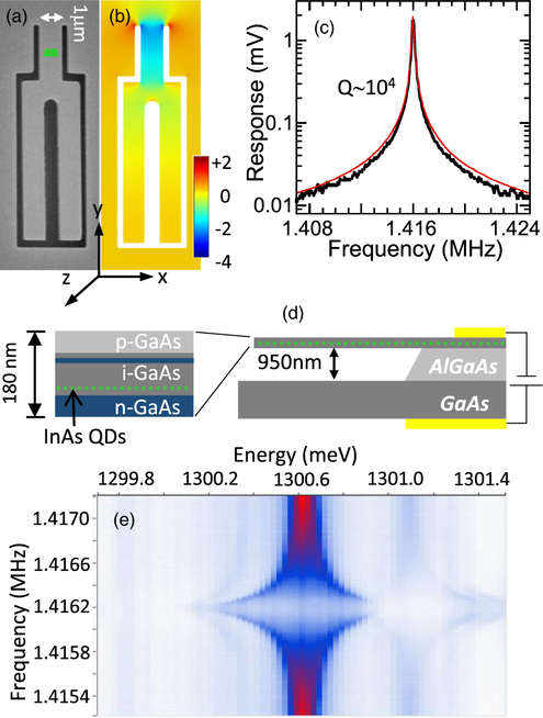
(a) Scanning electron micrograph of a tuning fork cantilever, with a green trapezoid indicating the estimated position of the QDs studied. (b) Finite element model of strain ϵyy within the cantilever at the QD depth for a displacement at the end of 160 nm. The color scale labels are in 10−4 fractional change in length. (c) Reflectivity response of a cantilever vs drive frequency, with a fit (red line) to the square root of a Lorentzian.(d) Schematic of the suspended sample structure with n-i-n-i-p diode. (e) Time-integrated PL color map as a function of emission energy and drive frequency at zero magnetic field for a negatively charged exciton.
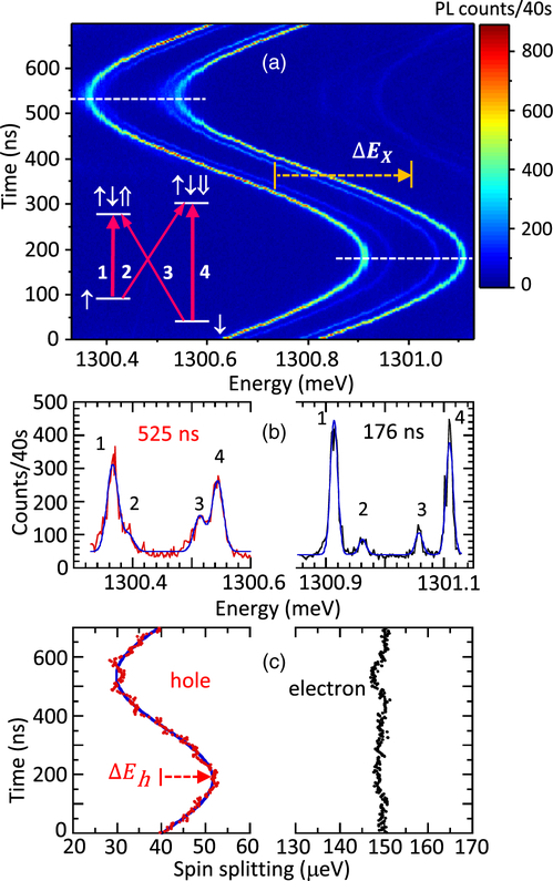
(a) Emission from X− in a 6 T Voigt magnetic field under resonant driving of the cantilever at 1.4162 MHz with 30 μW power at 923.5 nm. The emission is measured as a function of time, synchronized to the mechanical drive frequency. The inset shows a level diagram of X−, indicating the four possible transitions. The horizontal, dashed lines indicate the times of maximum and minimum energy, for which spectra are displayed in (b). (c) Hole and electron spin splittings as a function of time. The hole data are fit to a sine function (solid curve).
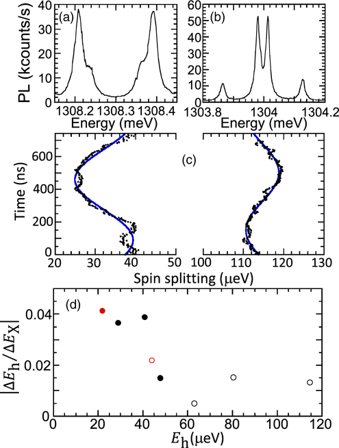
(a),(b) PL spectra of X− in a 6 T magnetic field for two other QDs, showing the variation in hole ɡ factor and polarization. The Fabry-Perot resolution is 9 μeV for these measurements. (c) Hole spin splitting (solid circles) as a function of time under mechanical driving for these two QD-cantilever systems, with sine function fits. The average drive power is 20 μW. (d) Change in the hole Zeeman energy divided by the change in the optical transition energy for 8 different QDs. For red circles, only one set of lines could be measured (inner or outer), so ΔEe is assumed to be negligible to find ΔEh. Closed (open) circles indicate the hole and optical transition shifts are in phase (out of phase). The average drive power varies from 20–40 μW for different QDs, and the PL laser power is 5 μW for all QDs.
References
-
- Schwab KC and Roukes ML, Phys. Today 58, No. 7, 36 (2005).
-
- Ramos T, Sudhir V, Stannigel K, Zoller P, and Kippenberg TJ, Phys. Rev. Lett 110, 193602 (2013). - PubMed
-
- Wilson-Rae I, Zoller P, and Imamoḡlu A, Phys. Rev. Lett 92, 075507 (2004). - PubMed
-
- Bennett SD, Kolkowitz S, Unterreithmeier QP, Rabl P,Jayich ACB, Harris JGE, and Lukin MD, New J. Phys 14, 125004 (2012). - PubMed
-
- Rabl P, Kolkowitz SJ, Koppens FHL, Harris JGE, Zoller P, and Lukin MD, Nat. Phys 6, 602 (2010).
Grants and funding
LinkOut - more resources
Full Text Sources