Review
. 2019 Jan 6;12(1):157.
doi: 10.3390/ma12010157.

Laser Cutting: A Review on the Influence of Assist Gas

Affiliations
Review

Laser Cutting: A Review on the Influence of Assist Gas

Antonio Riveiro et al. Materials (Basel). .

Abstract

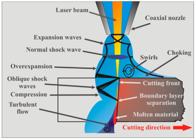
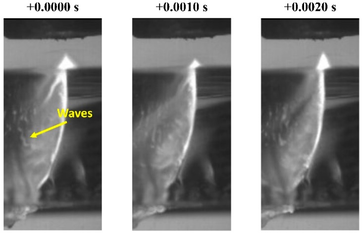
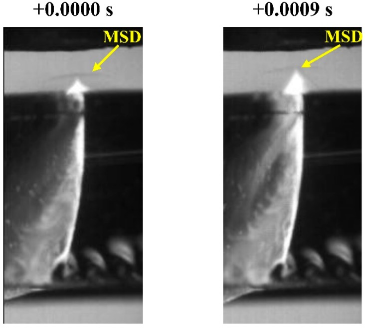
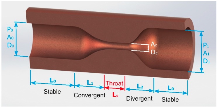
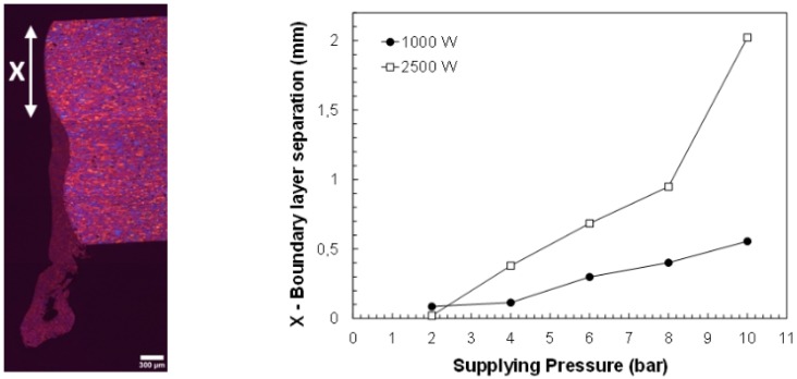
Assist gas plays a central role in laser fusion cutting. In this work, the aerodynamic interactions between the assist gas and the workpiece are reviewed. An insight into those phenomena that hinder the cutting quality and performance is provided. These phenomena include shock waves, choking, boundary layer separation, etc. The most relevant and promising attempts to overcome these common problems related to the gas dynamics are surveyed. The review of the current scientific literature has revealed some gaps in the current knowledge of the role of the assist gas dynamics in laser cutting. The assist gas interactions have been investigated only under static conditions; and the dynamic interaction with the molten material on the cutting front has not been addressed. New nozzle designs with improved efficiency of molten material removal are required to improve cut quality; and cutting speed in current industrial laser cutting machines; especially in those assisted by new high-brightness laser sources.

Keywords: assist gas; laser cutting; nozzles; shock waves.


Conflict of interest statement

Dynamic viscosity of the assist gas

Figures

Figure 1
Figure 1
Scheme of the forces acting on the molten material during laser fusion cutting.
Figure 2
Figure 2
Cutting edge and cross section of aluminum-cooper alloy samples (2024-T3) processed by means of a CO2 laser using a conventional cutting head working with three different supplying pressures (Processing parameters: Laser power P = 2500 W, cutting speed vc = 4000 mm/min, focal length f = 127 mm, stand-off Z = 1.5 mm, conical nozzle, nozzle diameter d = 2 mm, assist gas: argon).
Figure 3
Figure 3
Nozzle geometries commonly used for laser fusion cutting: (a) parallel, (b) conical, (c) converging, (d) converging-diverging, (e) annular, and (f) flat tipped. Reprinted with permission from [22]; Copyright 1986 SPIE.
Figure 4
Figure 4
(a) Scheme and (b) shadowgraph image of the free jet emerging from a conical nozzle commonly used in laser fusion cutting for an operating parameter range pe/pa > 1.89. Adapted with permission from [23]; Copyright 1998 Elsevier.
Figure 5
Figure 5
Variation of the pressure along the jet (air, conical nozzle, nozzle diameter d = 1.5 mm, gauge pressure p = 280 kPa) when the workpiece is moved away with regard to the laser beam. Reprinted with permission from [27]; Copyright 1984 ICALEO.
Figure 6
Figure 6
Dependence of the maximum cutting speed on the nozzle exit diameter for two supplying pressures (p = 5 and 10 bar) during laser cutting of aluminum-cooper alloys 3 mm in thickness (Processing parameters: Laser power P = 2500, stand-off Z = 1.5 mm, focal length f = 127 mm, conical nozzle, assist gas: argon). Adapted with permission from [30]; Copyright 2010 Elsevier.
Figure 7
Figure 7
Shadowgraph imaging of the Mach Shock Disk (MSD) formed at the entrance of a simulated cut kerf (Lateral view of the cut slot. Supplying pressure p = 8 bar, stand-off Z = 1 mm, nozzle diameter d = 2 mm).
Figure 8
Figure 8
Gas flow structure after exhausted by a conical nozzle just at the entry of the cut kerf.
Figure 9
Figure 9
Aerodynamic interactions during laser cutting using a conical nozzle showing the boundary layer separation. Adapted with permission from [30]; Copyright 2010 Elsevier.
Figure 10
Figure 10
Shear force distribution acting along the cutting front (when using a conical nozzle). A clear drop is noted after the boundary layer separation (estimated shear force in arbitrary units acting on the centerline of the cutting front for p = 1 MPa and p = 0.5 MPa). Adapted with permission from [49]; Copyright 2001 ICPE.
Figure 11
Figure 11
Two regions in the (a) cutting edge and in (b) the cross section are observed after the boundary layer separation (BLS) during laser cutting of an aluminum-copper alloy, and using a conical nozzle. Reprinted with permission from [30]; Copyright 2010 Elsevier.
Figure 12
Figure 12
Vortex formed in the exit of the cut kerf using (a) converging, and (b) cylindrical nozzles. (c) Influence of their presence in the cutting quality during laser cutting of 20 mm thick mild steel using an oxygen jet (Supplying pressure p = 0.6 bar). Reprinted with permission from [37]. Copyright 2008 IOP Publishing.
Figure 13
Figure 13
Waves on the molten material flowing along the cutting edge during laser cutting of glass (Processing conditions: Laser power P = 1400 W, cutting speed vc = 1400 mm/min, conical nozzle, nozzle diameter d = 2 mm, stand-off Z = 1.5 mm, assist gas: argon, supplying pressure p = 8 bar). Reprinted with permission [57]; Copyright 2011 IOP Publishing.
Figure 14
Figure 14
Displacement of the normal shock MSD due to the plume of ionized material emerging from the cut kerf (Processing conditions: Laser power P = 1400 W, cutting speed vc = 1000 mm/min, conical nozzle, nozzle diameter d = 2 mm, stand-off Z = 1.5 mm, assist gas: argon, supplying pressure p = 8 bar). Reprinted with permission [57]; Copyright 2011 IOP Publishing.
Figure 15
Figure 15
Scheme of a converging-diverging nozzle showing the different sections which compose the nozzle. Reprinted with permission from [69]; Copyright 1997 Elsevier.
Figure 16
Figure 16
Detachment of the boundary layer as a function of the assist gas pressure during laser cutting of aluminum-copper alloys. Reprinted with permission from [30]; Copyright 2010 Elsevier.
Figure 17
Figure 17
Schematic view of the (a) on-axis cutting process, (b) off-axis cutting process with the assist gas jet impinging normally to the workpiece, and (c) when the assist gas jet forms an angle with the laser beam.
Figure 18
Figure 18
A schematic view of the aerodynamic interactions for (a,b) different nozzle positions, and (c,d) different nozzle tilt angles. The arrow in (a) and (c) denotes the boundary layer separation. Adapted with permission from [89]; Copyright 1997 AIP Publishing.
Figure 19
Figure 19
Maximum cutting speed as a function of the nozzle angle for a sonic exit nozzle [89] and for a supersonic exit nozzle [91] during CO2 laser cutting of 3 mm mild steel and 3 mm Al-2024-T3 alloy respectively. Optimum nozzle angles range from 35° to 40° with regard to the laser beam.
Figure 20
Figure 20
(a) Parameters needed to define the nozzle contour in annular nozzles used for laser cutting and (b) shadowgraph of the free jet exhausted by an annular nozzle defined by d/D = 0.8, and α = 40° at an assistant pressure of p/pa = 9. (c) Coanda nozzle, and (d) Schlieren image of an impinging jet ejected by this kind of nozzle. Reprinted with permission from [97,102]; Copyright 1990 The Japan Society of Mechanical Engineers, 1992 SPIE.

References

    1. Hilton P.A. Early days of laser cutting; Proceedings of the Lasers in Material Processing; Munich, Germany. 18 August 1997; pp. 10–16.
    1. Eurostat . Energy Balance Sheets 2016 Data. 2018 ed. Eurostat; Luxembourg: 2018.
    1. Gutowski T., Dahmus J., Thiriez A. Electrical energy requirements for manufacturing processes; Proceedings of the 13th International of Life Cycle Engineering; Leuven, Belgium. 31 May–2 June 2006; pp. 623–627.
    1. Steen W. Laser Material Processing. 3rd ed. Springer; London, UK: 2003.
    1. Powell J. CO2 Laser Cutting. Springer; London, UK: 1993.

LinkOut - more resources