

Reconstruction of an informative railway wheel defect signal from wheel-rail contact signals measured by multiple wayside sensors
- PMID: 30662172
- PMCID: PMC6319541
- DOI: 10.1177/0954409718784362
Reconstruction of an informative railway wheel defect signal from wheel-rail contact signals measured by multiple wayside sensors
Abstract
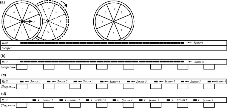
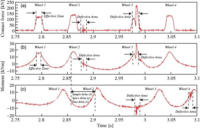
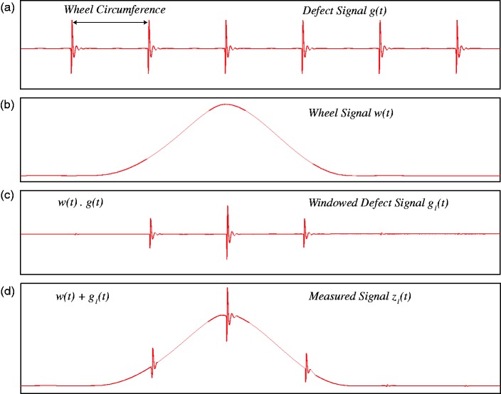
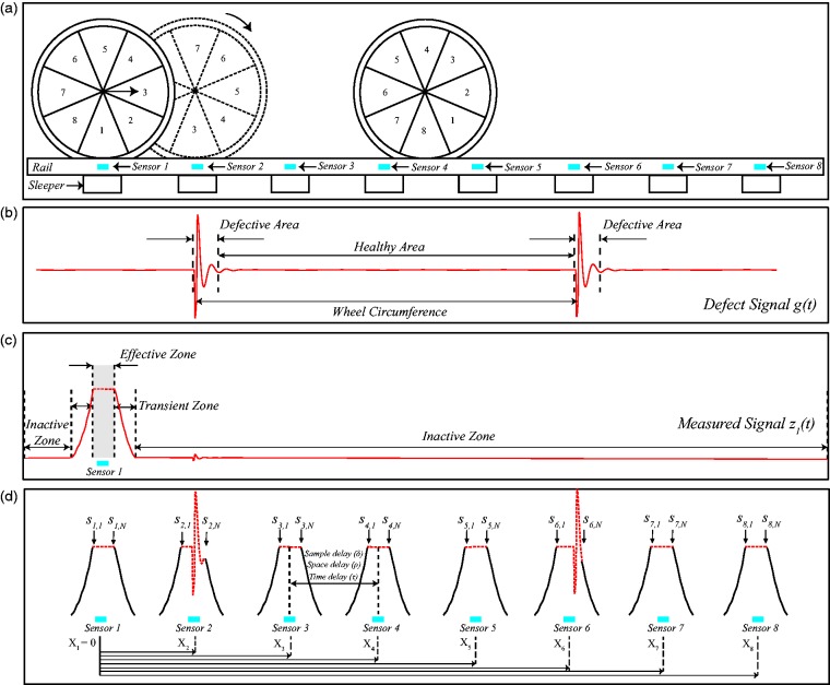
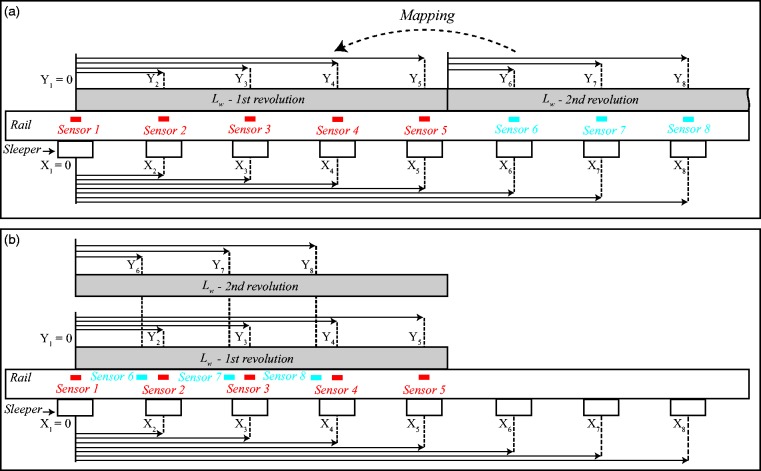
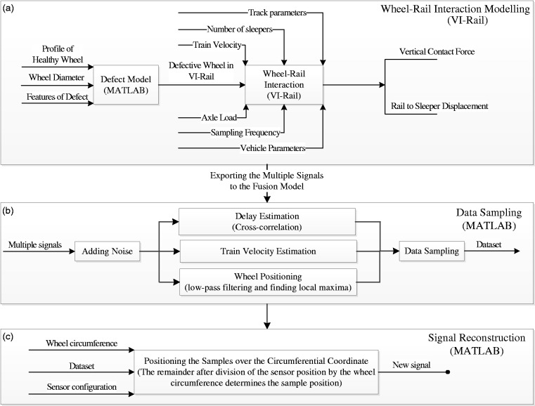
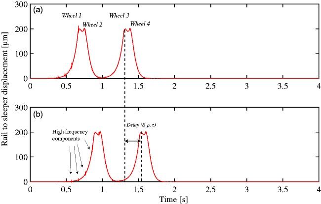
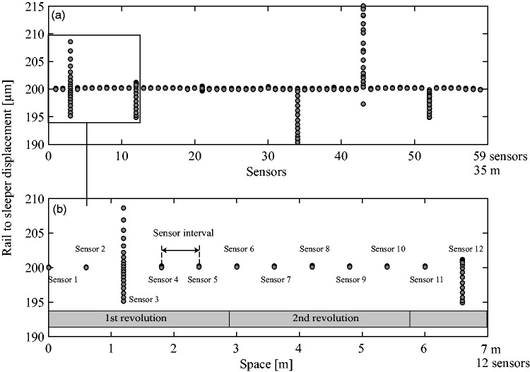
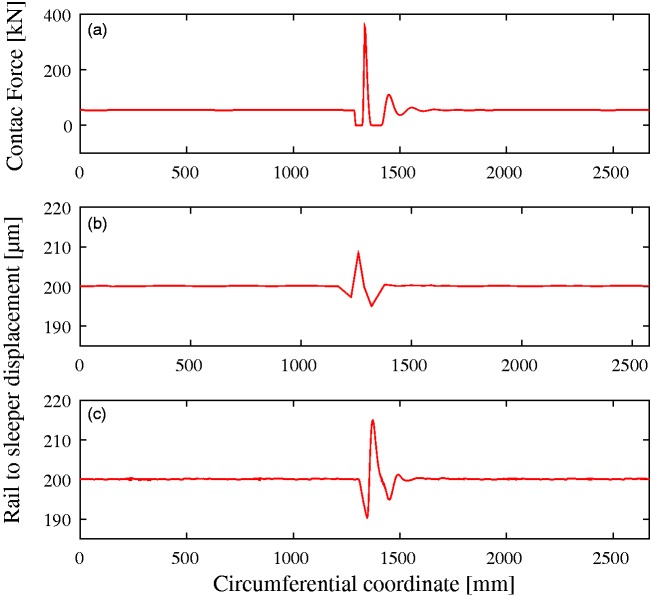
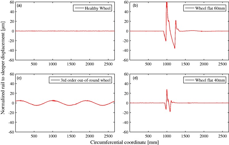
Wheel impact load detectors are widespread railway systems used for measuring the wheel-rail contact force. They usually measure the rail strain and convert it to force in order to detect high impact forces and corresponding detrimental wheels. The measured strain signal can also be used to identify the defect type and its severity. The strain sensors have a limited effective zone that leads to partial observation from the wheels. Therefore, wheel impact load detectors exploit multiple sensors to collect samples from different portions of the wheels. The discrete measurement by multiple sensors provides the magnitude of the force; however, it does not provide the much richer variation pattern of the contact force signal. Therefore, this paper proposes a fusion method to associate the collected samples to their positions over the wheel circumferential coordinate. This process reconstructs an informative signal from the discrete samples collected by multiple sensors. To validate the proposed method, the multiple sensors have been simulated by an ad hoc multibody dynamic software (VI-Rail), and the outputs have been fed to the fusion model. The reconstructed signal represents the contact force and consequently the wheel defect. The obtained results demonstrate considerable similarity between the contact force and the reconstructed defect signal that can be used for further defect identification.
Keywords: Railway; condition monitoring; contact; defect; signal reconstruction; wheel.
Figures
Similar articles
-
Recent Advances in Wayside Railway Wheel Flat Detection Techniques: A Review.Sensors (Basel). 2023 Apr 12;23(8):3916. doi: 10.3390/s23083916. Sensors (Basel). 2023. PMID: 37112257 Free PMC article. Review.
-
In-Service Detection and Quantification of Railway Wheel Flat by the Reflective Optical Position Sensor.Sensors (Basel). 2020 Sep 2;20(17):4969. doi: 10.3390/s20174969. Sensors (Basel). 2020. PMID: 32887346 Free PMC article.
-
Identification method of wheel-rail two-point contact state in switch area.Sci Rep. 2025 Jan 29;15(1):3657. doi: 10.1038/s41598-025-85687-8. Sci Rep. 2025. PMID: 39881128 Free PMC article.
-
Wayside Detection of Wheel Minor Defects in High-Speed Trains by a Bayesian Blind Source Separation Method.Sensors (Basel). 2019 Sep 14;19(18):3981. doi: 10.3390/s19183981. Sensors (Basel). 2019. PMID: 31540129 Free PMC article.
-
A Review of NDT Methods for Wheel Burn Detection on Rails.Sensors (Basel). 2023 May 31;23(11):5240. doi: 10.3390/s23115240. Sensors (Basel). 2023. PMID: 37299966 Free PMC article. Review.
Cited by
-
Safety evaluation of rail transit vehicle system based on improved AHP-GA.PLoS One. 2022 Aug 24;17(8):e0273418. doi: 10.1371/journal.pone.0273418. eCollection 2022. PLoS One. 2022. PMID: 36001603 Free PMC article.
-
EMD-Based Methodology for the Identification of a High-Speed Train Running in a Gear Operating State.Sensors (Basel). 2018 Mar 6;18(3):793. doi: 10.3390/s18030793. Sensors (Basel). 2018. PMID: 29509690 Free PMC article.
-
Recent Advances in Wayside Railway Wheel Flat Detection Techniques: A Review.Sensors (Basel). 2023 Apr 12;23(8):3916. doi: 10.3390/s23083916. Sensors (Basel). 2023. PMID: 37112257 Free PMC article. Review.
References
-
- Chong SY, Lee JR, Shin HJ. A review of health and operation monitoring technologies for trains. Smart Struct Syst 2010; 6: 1079–1105.
-
- Alemi A, Corman F, Lodewijks G. Condition monitoring approaches for the detection of railway wheel defects. Proc IMechE, Part F: J Rail and Rapid Transit 2017; 231: 961–981.
-
- Partington W. Wheel impact load monitoring. Proc ICE Transp 1993; 100: 243–245.
-
- Brickle B, Morgan R, Smith E, et al. Identification of existing and new technologies for wheelset condition monitoring. London, United Kingdom: Technical report, Rail Safety and Standards Board (RSSB), 2008.
-
- Stratman B, Liu Y, Mahadevan S. Structural health monitoring of railroad wheels using wheel impact load detectors. J Fail Anal Prev 2007; 7: 218–225.
LinkOut - more resources
Full Text Sources