Review
. 2019 Sep;131(3):716-749.
doi: 10.1097/ALN.0000000000002583.

Imaging the Injured Lung: Mechanisms of Action and Clinical Use

Affiliations
Review

Imaging the Injured Lung: Mechanisms of Action and Clinical Use

Maurizio Cereda et al. Anesthesiology. 2019 Sep.

Erratum in

Abstract

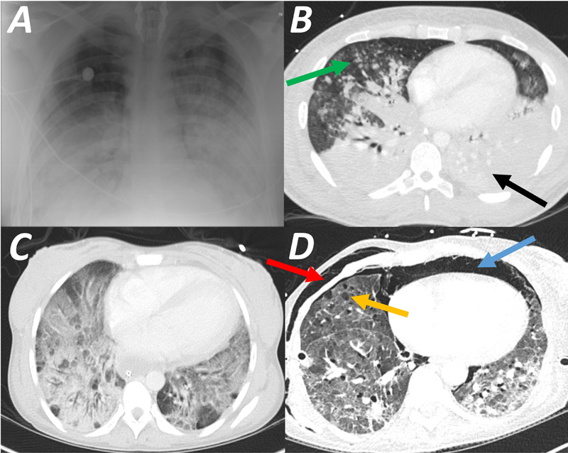
Acute respiratory distress syndrome (ARDS) consists of acute hypoxemic respiratory failure characterized by massive and heterogeneously distributed loss of lung aeration caused by diffuse inflammation and edema present in interstitial and alveolar spaces. It is defined by consensus criteria, which include diffuse infiltrates on chest imaging-either plain radiography or computed tomography. This review will summarize how imaging sciences can inform modern respiratory management of ARDS and continue to increase the understanding of the acutely injured lung. This review also describes newer imaging methodologies that are likely to inform future clinical decision-making and potentially improve outcome. For each imaging modality, this review systematically describes the underlying principles, technology involved, measurements obtained, insights gained by the technique, emerging approaches, limitations, and future developments. Finally, integrated approaches are considered whereby multimodal imaging may impact management of ARDS.


Conflict of interest statement

CONFLICTS OF INTEREST: The authors declare no competing interests. D. W. Kaczka and J. Herrmann are co-inventors on a pending patent involving multifrequency oscillatory ventilation (MFOV). In addition, they are cofounders and shareholders of OscillaVent, Inc. B.P. Kavanagh and T. Yoshida have a patent pending on a device for mechanical ventilation.

Figures

Figure 1:
Figure 1:
Chest imaging in patients with Acute Respiratory Distress Syndrome (ARDS). Plain chest radiograph (CXR, Panel A) demonstrates symmetric widespread hazy infiltrates. In the same patient computed tomography scan (CT, Panel B) confirms the bilateral infiltration observed on plain CXR; however, the infiltrate is predominantly in the dorsal lung (black arrow), and the ventral lung regions are aerated (‘baby lung’, green arrow). Panel C is a CT scan showing typical ground glass opacities, indicating severely decreased aeration, but without complete loss of gas content. Panel D is a CT scan of a patient 16 days after the onset of ARDS, showing diffuse interstitial thickening predominantly at the lung bases, suggesting evolving fibrosis; in addition, ventral bullae (orange arrow), pneumomediastinum (blue arrow), and soft tissue emphysema (red arrow) represent barotrauma from mechanical ventilation.
Figure 2:
Figure 2:
Schematic illustration of CT densities relative to air, normal lung, water and bone (Panel A). The smallest unit of imaged tissue is called a voxel (≈ 1 mm3), and the average density, expressed as Hounsfield Units (HU), of each voxel is determined by its contents. Higher density contents absorb more radiation and the image is whiter, whereas lower density contents absorb less radiation and the image is darker. If a voxel was composed entirely of air, water or bone it would have densities of -1000 HU, 0 HU and +700 HU, respectively. The density of fat, water and soft tissue are similar (fat ≤ water ≤ soft tissue), and normally aerated lung tissue (corresponding approximately to 50-70% air, 30-50% tissue) has a density of < -500 HU. Therefore, a hyperinflated region of lung (more air, less tissue) would have a density of far less than -500 HU (generally < -900 HU), whereas an area with substantial consolidation or atelectasis will have density of more than -100 HU. Areas with decreased (but not eliminated) aeration, called ‘poorly aerated’ lung, have density in the range of -500 to -100 HU. Panel B illustrates a range of possible content combinations within a single voxel. It is important to understand that the maximum resolution for CT is limited by the size of the voxel, and each voxel can only yield a single ‘net’ value for density. Thus, the illustrated voxels, while having different individual constitutions, each have a similar ‘average’ density expressed as HU.
Figure 3:
Figure 3:
Schematic showing the process of image registration between end-inspiratory (EI) and end-expiratory (EE) images (Upper Panels - Schematic; Lower Panels - representative CT slices). The end-expiratory image is expanded in three dimensions to align all visible tissue features, including airways and blood vessels, to the target end-inspiratory image. With registration of tissue points, it is then possible to track the displacement that any point in the image undergoes during each tidal deflation (e.g., the red and yellow dots). The product of the registration is thus a ‘warped’ (i.e. constrained fit) end-expiratory image. An example of image registration performed on end-inspiratory and end-expiratory CT scans obtained in a ventilated rat after lung injury is shown (Bottom Panel; see also Supplemental Digital content 1).
Figure 4:
Figure 4:
Dynamic computed tomography (CT) illustrates the real-time spatial distribution of lung aeration during mechanical ventilation in experimental lung injury. Lung injury was induced by oleic acid infusion (see video - Supplemental Digital Content 2). Pressure-controlled ventilation (driving pressure 20 cmH2O, rate 32 min−1, Inspired O2 40%) with lower PEEP (5 cmH2O, Panel A) or higher PEEP (10 cmH2O, Panel B) was used. In each panel, [i] end-inspiratory CT (transverse, sagittal, coronal planes), [ii] minimum intensity projection voxels, and [iii] time- varying fractions of lung at normally-aerated, poorly-aerated and non-aerated levels are illustrated. The following features are observed. Hyperaerated tissue (not visible) accounted for <1% of lung voxels at either level of PEEP. The intra-tidal changes in normal, poorly and non-aerated fraction were 15, 10 and 5%, respectively, at the two PEEP levels. However, there was a nearly two-fold increase in non-aerated tissue at the lower PEEP, as well as noticeable flooding of large bronchi in the right lung and arterial hemoglobin O2 saturation was 92 vs. 63% with PEEP 10 vs. 5 cmH2O. Normal, poor and non-aeration is considered: −900 to −500, −500 to −100, and above −100 HU, respectively.
Figure 5:
Figure 5:
End-expiratory CT scans obtained in a patient with ARDS at high PEEP (20 cmH2O, Panel A) and low PEEP (5 cmH2O, Panel B). In each panel, three values of inspiratory plateau pressure (Pplat 30, 35 and 45 cmH2O) are targeted, and in each case the resultant driving pressure (ΔP = Pplat - PEEP) is indicated below each image. For each Pplat, atelectasis was more pronounced when the PEEP was lower, irrespective of the inspiratory ΔP. The CT illustrates that alveolar recruitment achieved by high inflation pressure is not maintained during expiration unless stabilized by sufficient PEEP. Reproduced with permission, Ref. 110.
Figure 6.
Figure 6.
Parametric response maps (PRMs) are constructed where each voxel is represented by a single point, the coordinates of which correspond to the density of the voxel (in HU) at end-expiration (X-axis) and at end-inspiration (Y-axis). In a normal rat lung (Upper Left Panel), almost all of the voxels (i.e. density of lung tissue) are clustered around -700 HU (in both axes); thus the density is uniform as expected in normal lung, and there is ‘stable density’, i.e. little overall difference in between inspiration and expiration (green box). In the injured rat lung (Upper Right Panel), most voxels remain within the ‘normal’ lung distribution (green box). However, many voxels fall in a distribution indicating near-normal density at and-inspiration (−300 to −700 HU) and predominantly high density (minimally aerated lung; 0 to −600 HU) at end-expiration; this profile corresponds to ‘unstable inflation’ (red box). Finally, several voxels are clustered in the upper rightmost corner, i.e. high density (range of -100 HU) in end-inspiration and in end-expiration. This represents fixed consolidation (no aeration, no recruitment; yellow box). PRMs from patients with ARDS are shown (Lower Panels); while both patients have voxels indicating fixed atelectasis (upper right corners), the patient who survived (Lower Left Panel) had more voxels in the ‘normal’ range, and fewer voxels indicating ‘unstable inflation’, than the patient who did not survive (Lower Right Panel). Reproduced with permission Ref. 14.
Figure 7.
Figure 7.
Positrons (β+) are emitted from the tracer and interact with electrons (β-) belonging to the local tissue, causing an annihilation that produces two photons (ϒ) travelling in opposite directions. When two photons are simultaneously sensed by the PET machine on two opposite detectors, the ‘event’ causing their emission is considered ‘true’ and their origin is plotted on the image.
Figure 8:
Figure 8:
Paired Computed tomography (CT, Upper Left Panel) and [18F]-fluoro-2-deoxy-d-glucose (18FDG) positron emission tomography (PET, Lower Left Panel) from a patient with ARDS. A high level of 18FDG activity is seen in the in ventral lung in the PET scan (Yellow Box 1) that appears normally aerated in the CT scan (‘baby lung; Black Box 1). Paired electrical impedance tomography (EIT, Upper Right Panel) and PET (Lower Right Panel) images are shown from a pig with lung injury ventilated with low tidal volume and low PEEP, while performing strong inspiratory effort. The EIT image shows regions of maximum ventilation (grey shade) in dependent lung near the diaphragm, and the PET image shows high FDG activity, indicating inflammation, in the same dependent regions. Reproduced with permission from Refs. 168 and 170.
Figure 9:
Figure 9:
Nuclear spin is an inherent property whereby nuclei spontaneously rotate; this generates the signal in magnetic resonance imaging (MRI). The schematic illustrates the impact of a magnetic field and hyperpolarization (Upper Panels). In the absence of a magnetic field (Upper Left Panel) the spins are haphazard; but, in the presence of a magnetic field (Upper Mid Panel), the spins are aligned with the direction of that field (or in the opposite direction: ‘anti-aligned’). The direction is called the B vector. Aligned and anti-aligned spins cancel each other in pairs (paired yellow circles); but a small proportion of spins remain unpaired (green circles), and these unpaired spins generate the MRI signal. Hyperpolarization generates a far larger fraction of unpaired spins (Upper Right Panel) and this greatly enhances the signal. The Lower Panel illustrates the impact of an external radiofrequency energy pulse on the magnetic field. The energy pulse modifies (‘flips’) the axis of the spin and changes its direction, and over time the spin recovers its original orientation. However, during this recovery time, the MRI signal is collected, and because individual tissues have different recovery times, a tissue-by-tissue contrast is created by the MRI.
Figure 10:
Figure 10:
The apparent diffusion coefficient (ADC) is a metric of the space across which a molecule can diffuse; thus in the lung, this is considered to be a correlate of the average volume of the alveolus. Compared with normal rat lung (Panel A - Left), the ADC is far greater in a lung with lung injury (Panel A- Right). When alveoli are uniformly and normally inflated, a relatively low value of ADC is recorded at end-inspiration (Panel B - Left). With atelectasis (Panel B - Right), hyperpolarized gas cannot reach non-ventilated alveoli and can only reach the ventilated units, which are hyperinflated; thus a higher value of ADC is recorded. Coronal lung images of lung slices illustrate the differences among CT density, hyperpolarized 3He Density, and ADC before (Panel C, Upper) and after (Panel C, Lower) surfactant depletion in a rat lung. The CT density is low in normal lung, and is increased following surfactant depletion where widespread atelectasis (complete - white, partial - grey) is apparent. The 3He density image shows a homogeneously bright signal in normal lung reflecting uniform distribution of inhaled gas; however, after surfactant depletion, there are multiple areas of absent signal representing areas that are inaccessible to inspired gas because of complete atelectasis. The ADC maps in normal lung show mostly mid to low values (i.e. <0.15 cm2·sec−1); but, following surfactant depletion, areas of complete atelectasis are not visualized, whereas ventilated airspaces are easily seen and have high ADC values (i.e. are hyperinflated; >0.25 cm2·sec−1). This illustrates the high sensitivity of ADC to detect enlarged (i.e. over-distended) airspaces that appears on MRI as a homogeneous, high signal, even when surrounded by collapsed or partially deflated units; and, it contrasts to CT where the density is averaged within each voxel.
Figure 11:
Figure 11:
Electrical impedance tomography (EIT) determines the distribution of intra-thoracic impedance (Z) by applying a known alternating current (I) to an initial pair of electrodes and measuring the resulting surface potentials (voltage, V) at each of the remaining 13 pairs of electrodes (Panel A). Next, the current is applied to the adjacent electrode pair of electrodes and the V recorded at the other electrodes; this cycle is repeated for one cycle of current applications, resulting in one set of EIT raw data expressed as inspiratory cyclic changes in impedance (ΔZ) (Adapted from Drager). The cycle takes 0.02 seconds; it is repeated continuously in each of the circuits in sequence, and the impedance is continuously measured. Because of the multiple circuits around the chest, ΔZ can be localized approximately to each of the quadrants. Because an increase in circuit impedance reflects an inspiratory increase in aeration, ΔZ reflects ventilation of the region in question. Panel B demonstrates the distribution of ventilation using EIT, and the corresponding aeration in CT images, in a pig with lung injury. At PEEP 12 cmH2O, distribution of ventilation is homogeneous (left upper). The white-dots identify the mid-line bisecting the thorax. The center of ventilation (COV) is calculated as [(ΔZ in dorsal half of lung) x 100]/[ΔZ in whole lung];187 if the mid-line is positioned, the % of ventilation that is dorsal is shown on the EIT display (and reflects COV) so that off-line calculation is not necessary. In this example (left upper), with PEEP 12 cmH2O, COV is 44%, and the corresponding CT shows no lung collapse (left lower). In contrast, when the PEEP is reduced to 4 cmH2O, ventilation is shifted to non-dependent lung at and COV is now 25% (right upper), and the corresponding CT confirmed the presence of dorsal atelectasis in the same region (right lower).
Figure 12:
Figure 12:
Schematic and still images of lung ultrasound in normal lung (Panel A), interstitial syndrome (Panel B) and alveolar syndrome (Panel C). In the normally aerated lung (Panel A), the findings include a homogenous pleural line (uppermost horizontal white line in image), the presence of an A line (i.e. short horizontal white line in mid-image, an artefact from the pleural line), lung sliding (see respiratory changes seen in the dynamic video- Supplemental Digital Content 6), and a lung pulse (see cardiac changes seen in the dynamic video- Supplemental Digital Content 6). The interstitial syndrome (Panel B) involves loss of lung aeration and is of two types. The ‘B1’ pattern, corresponding to moderate loss of aeration, has 3 or more B-lines (vertical) per intercostal space, whereas the ‘B2’ pattern, corresponding to more severe loss of aeration, has multiple coalescent B-lines per intercostal space. Lung consolidation (Panel C), indicates substantially increased density with almost complete loss of aeration. This is characterized by an anechoic (i.e. tissue-like) image arising from the pleural line.

Similar articles

Cited by

References

    1. Ashbaugh DG, Bigelow DB, Petty TL, Levine BE: Acute respiratory distress in adults. Lancet 1967; 2: 319–323 - PubMed
    1. Gattinoni L, Pesenti A: ARDS: the non-homogeneous lung; facts and hypotheses. Intensive and Crit Care Digest 1987; 6: 1–4
    1. Elicker BM, Jones KT, Naeger DM, Frank JA: Imaging of Acute Lung Injury. Radiol Clin North Am 2016; 54: 1119–1132 - PubMed
    1. Gattinoni L, Pesenti A, Avalli L, Rossi F, Bombino M: Pressure-volume curve of total respiratory system in acute respiratory failure. Computed tomographic scan study. Am Rev Respir Dis 1987; 136: 730–736 - PubMed
    1. Puybasset L, Cluzel P, Chao N, Slutsky AS, Coriat P, Rouby JJ: A computed tomography scan assessment of regional lung volume in acute lung injury. The CT Scan ARDS Study Group. Am J Respir Crit Care Med 1998; 158: 1644–1655 - PubMed

Publication types

MeSH terms