Review
. 2015 Sep 30;1(2):135-161.
doi: 10.3390/gels1020135.

Magnetic Gel Composites for Hyperthermia Cancer Therapy

Affiliations
Review

Magnetic Gel Composites for Hyperthermia Cancer Therapy

Marleen Häring et al. Gels. .

Abstract

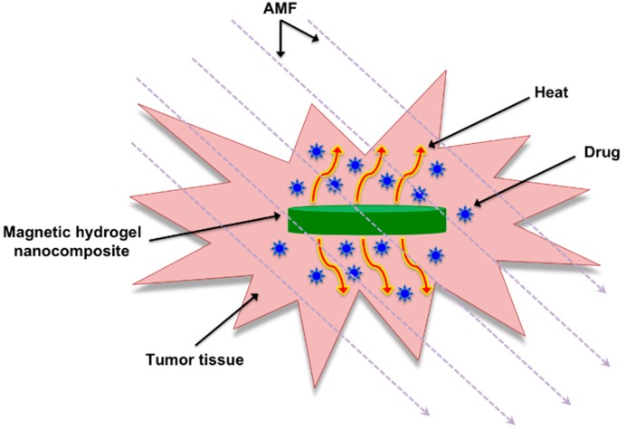
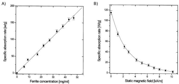
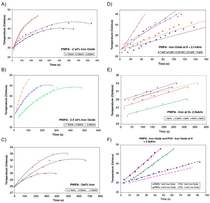
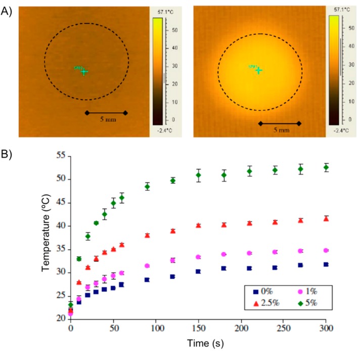
Hyperthermia therapy is a medical treatment based on the exposition of body tissue to slightly higher temperatures than physiological (i.e., between 41 and 46 °C) to damage and kill cancer cells or to make them more susceptible to the effects of radiation and anti-cancer drugs. Among several methods suitable for heating tumor areas, magnetic hyperthermia involves the introduction of magnetic micro/nanoparticles into the tumor tissue, followed by the application of an external magnetic field at fixed frequency and amplitude. A very interesting approach for magnetic hyperthermia is the use of biocompatible thermo-responsive magnetic gels made by the incorporation of the magnetic particles into cross-linked polymer gels. Mainly because of the hysteresis loss from the magnetic particles subjected to a magnetic field, the temperature of the system goes up and, once the temperature crosses the lower critical solution temperature, thermo-responsive gels undergo large volume changes and may deliver anti-cancer drug molecules that have been previously entrapped in their networks. This tutorial review describes the main properties and formulations of magnetic gel composites conceived for magnetic hyperthermia therapy.

Keywords: cancer therapy; composites; drug delivery; hydrogel; hyperthermia; magnetic nanoparticles.


Conflict of interest statement

The authors declare no conflict of interest.

Figures

Figure 1
Figure 1
Basic illustration of thermo-responsive magnetic gel composites that can be heated upon exposure to an AMF allowing for the controlled delivery of entrapped drugs.
Figure 2
Figure 2
Main preparation methods of magnetic hydrogels. (A) The blending method: the magnetic nanoparticles are mixed with a hydrogel precursor solution at a certain molar ratio and cross-linked; (B) the in situ preparation method: the magnetic nanoparticles are fabricated via an in situ precipitation in the network of the polymer hydrogel after the cross-linking; and (C) the grafting-onto method: grafting several functional groups onto the surface of the magnetic nanoparticles to be used as cross-linkers. Adapted with permission from reference [32]. Copyright © 2013 Wiley-VCH.
Figure 3
Figure 3
Photomicrographs (right: 25×, left: 200×) of Swiss nude mice subcutaneous xenografts Co112 injected with an EVAL-based formulation incorporating 40% w/v of magnetic nanoparticles. Empty arrow heads (Δ) indicate the implant; t, the tumor tissue; and n, the areas of necrosis. On the left, the central distribution of the implant in the tumor with extensions toward its periphery. This high microparticles load masks some characteristics of type III microstructure in the large peripheral rim concentrating microparticles (dashed lined box), where implants devoid of microparticles show a remarkably thin initially precipitated skin layer and a porous sub-layer. However, lacunas observed at low magnification in the center of implant (C) support type III microstructure. Adapted with permission from reference [42]. Copyright © 2010 Elsevier.
Figure 4
Figure 4
Left panel: (A) Photograph of bulk gels with various shapes; (B) SEM images of scaffold with various pore size (average diameter from left to right: 700, 300 and 20 μm) and pore connectivity in the ferrogels; (C) TEM images of iron oxide nanoparticles in the gel at different concentrations (left: 13 wt %; right: 4 wt %); and (D) schematic plots of the nanoparticles coated with Pluronic F127 (left) and alginate covalently cross-linked by AAD and coupled with RGD peptides (right). Right panel: (A) schematic plot of gel deformation and resulting water convection inducing cell release from macroporous gels; (B) cumulative release profiles of fibroblasts from macroporous ferrogels with 100% (cross), 50% (circle) and 10% (square) of the baseline RGD density, following application of cycled magnetic field; and (C) in vivo fluorescence images of mice implanted with macroporous ferrogel containing mouse mesenchymal stem cells stained with DiOC18 before (I) and after (II) magnetic stimulation. The control case was subjected to no magnetic stimulation. The positions of the gel discs are indicated by circles on the figure. Adapted with permission from reference [49]. Copyright © 2011 National Academy of Sciences.
Figure 5
Figure 5
Photographs of chi/aga-1.5 ferrogels loaded with magnetic nanoparticles at 2.0% and 5.0% (w/v) and their SEM images corresponding to the (a) surface and (b) cross section. Adapted with permission from reference [51]. Copyright © 2015 MDPI.
Figure 6
Figure 6
Top: Reaction scheme of the formation of CMC hybrid hydrogels. The reaction involves the formation of an amide bond between the carboxylic groups of CMC and the amine groups of the amino-functionalized metal oxide nanoparticles (cross-linkers) in the presence of EDC and NHS; Bottom: Ball-and-stick molecular model of DOX (doxorubicin) and comparison of its release from Fe3O4-CMC hydrogel composite in NaCl 0.15 M in the absence of magnetic field (circles), in the presence of an AMF (squares) and with SMF (triangles). Adapted with permission from reference [52] and reference [54]. Copyrights © 2011 Royal Society of Chemistry and © 2015 MDPI, respectively.
Figure 7
Figure 7
Schematic illustration of DOX-GO/IONP/PEI-gel. MHT = Magnetic hyperthermia. Reprinted with permission from reference [57].
Figure 8
Figure 8
(A) Time-dependent biodistribution assay in vivo of S180 tumor-bearing mice. (A) FX imaging in vivo; ((A1) IR 783, i.v.; (A2) DOXGO/IONP/PEI-gel, intratumorally injected); (B) the drug distribution of (B1) DOX (free IR783) ,and (B2) DOX-GO/IONP/PEI-gel (intratumorally injected) in tumor tissues (n = 6). Reprinted with permission from reference [57].
Figure 9
Figure 9
(A) SAR of gel samples with varying total ferrite concentrations in an AC of 217 kHz and 9.6 kA/m; and (B) dependence of SAR of a gel sample (ferrite concentration 30 g/L) on the SMF applied in the direction perpendicular to an AC field of 217 kHz and 9.6 kA/m. Adapted with permission from reference [14]. Copyright © 2001 Elsevier.
Figure 10
Figure 10
(A) Temperature vs. time for PNIPA-2 wt % iron oxide; (B) temperature vs. time for PNIPA-2.5 wt % iron oxide; (C) temperature vs. time for PNIPA-2 wt % iron; (D) temperature vs. time for PNIPA-iron oxide at H = 2.5 kA/m; (E) temperature vs. time for PNIPA-iron at H = 2.5 kA/m; and (F) temperature vs. time for PNIPA-iron oxide and PVA-iron oxide at H = 2.5 kA/m. Adapted with permission from reference [59]. Copyright © 2009 Springer.
Figure 11
Figure 11
(A) Heating effect of nanocomposites in electromagnetic field: IR image of 5 wt % particle disc at 0 s (left) and at 60 s (right). The dotted circle shows the disc area; and (B) temperature increase of nanocomposites with varying particle loadings subjected to an electromagnetic field. % represents the particle loading by weight in the NIPAAm-PEG400DMA nanocomposite. Adapted with permission from reference [61]. Copyright © 2008 Elsevier.
Figure 12
Figure 12
Structures of PEGMMA and PEGDMA (top) and swelling analysis results for all PEG hydrogel nanocomposites at 22, 37, 43, and 63 °C showing the volume swelling ratio (Q) for each system. Adapted with permission from reference [62]. Copyright © 2010 Elsevier.
Figure 13
Figure 13
M059K glioblastoma multiform/hydrogel heating results. Images (AI) represent fluorescent microscopy images after Live/Dead assay of M059K cells, where (A,B) are at the center of the Petri dish; (DF) are at the interface between live and dead cells and (GI) are at the outer edge, unaffected by heat. The first column of images are for cells exposed to a DM gel (50 mol % PEG200MMA, 50 mol % TEGDMA) at 297 kHz and 25 kA/m for 5 min, the middle column are of cells exposed to an AMF only at 297 kHz and 25 kA/m for 5 min and the right column is of cells not exposed to gels or an AMF; Images (J,K) represent IR images after the cells had been heated with the gel for 5 min (J) and exposed to an AMF for 5 min (K). Adapted with permission from reference [62]. Copyright © 2010 Elsevier.
Figure 14
Figure 14
(A) Synthesis of poly(β-amino ester) from PEGDA and IBA; (B) scheme of AMF setup; and (C) thermal analysis of 0:100 2EG-IBA magnetic hydrogel nanocomposite with time upon exposure to an AMF of 17.4 kA/m and 294 kHz for 5 min (n = 3 ± SD). Adapted with permission from reference [64]. Copyright © 2012 Elsevier.
Figure 15
Figure 15
Ball-and-stick molecular model of PTX (paclitaxel, Taxol®) and its release from hydrogel nanocomposites over time via HPLC. n = 3 ± SD. Adapted with permission from reference [64]. Copyright © 2013 Taylor & Francis.
Figure 16
Figure 16
(A) Heat generation of a magnetic hydrogel nanocomposite disc subjected to AMF is by magnetic nanoparticles and loss is by convection to surrounding air; and (B) temperature profile at steady state for hydrogel disc (radius 5 mm, thickness 2 mm, particles 5 wt %, AMF 25 kA/m) and surrounding tissue in xz plane along y = 0. Adapted with permission from reference [65]. Copyright © 2011 American Institute of Chemical Engineers.
Figure 17
Figure 17
(A) MRI images of the microrobot at four different positions. The artifact caused by the microrobot approximates the magnetic dipole field that it induces, making it possible to track its position; and (B) overview of the magnetic resonance tracking and guiding platform integrated with the magnetic hyperthermia system. The patient can easily be transferred from one system to another for a complete delivery procedure. Adapted with permission from reference [66]. Copyright © 2011 Taylor & Francis.
Figure 18
Figure 18
(A) Synthesis of Fe3O4 nanoparticles throughout NIPAM-AmPS hydrogel networks. (B) Left: Heating curves of pure NI (system without AmPS; black squares), NIAM (hydrogel without nanoparticles; red circles) and NIAM-Fe3O4 (composite hydrogel; green triangles). Right: Heating curves for different hydrogel magnetic nanocomposite at fixed apparent current (I = 300 A). Adapted with permission from reference [68]. Copyright © 2015 Elsevier.

Similar articles

Cited by

References

    1. Baronzio G.F. Hyperthermia in Cancer Treatment: A Primer. Springer; Berlin, Germany: 2006.
    1. Hildebrandt B., Wust P., Ahlers O., Dieing A., Sreenivasa G., Kerner T., Felix R., Riess H. The cellular and molecular basis of hyperthermia. Crit. Rev. Oncol. Hematol. 2002;43:33–56. - PubMed
    1. Freeman C., Edward C.H., Brady L.W., Wazer D.E. Perez and Brady’s Principles and Practice of Radiation Oncology. Wolters Kluwer Health/Lippincott Williams & Wilkins; Philadelphia, PA, USA: 2008. pp. 637–644.
    1. Shinkai M. Functional magnetic particles for medical application. J. Biosci. Bioeng. 2000;94:606–613. doi: 10.1016/S1389-1723(02)80202-X. - DOI - PubMed
    1. Sneed P.K., Stauffer P.R., McDermott M.W., Diederich C.J., Lamborn K.R., Prados M.D., Chang S., Weaver K.A., Spry L., Malec M.K., et al. Survival benefit of hyperthermia in a prospective randomized trial of brachytherapy boost +/− hyperthermia for glioblastoma multiforme. Int. J. Radiat. Oncol. Biol. Phys. 1998;40:287–295. doi: 10.1016/S0360-3016(97)00731-1. - DOI - PubMed

LinkOut - more resources