Review
. 2018 Nov 19;6(2):1801505.
doi: 10.1002/advs.201801505. eCollection 2019 Jan 23.

Rational Design and Construction of Cocatalysts for Semiconductor-Based Photo-Electrochemical Oxygen Evolution: A Comprehensive Review

Affiliations
Review

Rational Design and Construction of Cocatalysts for Semiconductor-Based Photo-Electrochemical Oxygen Evolution: A Comprehensive Review

Xiao-Ting Xu et al. Adv Sci (Weinh). .

Abstract

Photo-electrochemical (PEC) water splitting, as an essential and indispensable research branch of solar energy applications, has achieved increasing attention in the past decades. Between the two photoelectrodes, the photoanodes for PEC water oxidation are mostly studied for the facile selection of n-type semiconductors. Initially, the efficiency of the PEC process is rather limited, which mainly results from the existing drawbacks of photoanodes such as instability and serious charge-carrier recombination. To improve PEC performances, researchers gradually focus on exploring many strategies, among which engineering photoelectrodes with suitable cocatalysts is one of the most feasible and promising methods to lower reaction obstacles and boost PEC water splitting ability. Here, the basic principles, modules of the PEC system, evaluation parameters in PEC water oxidation reactions occurring on the surface of photoanodes, and the basic functions of cocatalysts on the promotion of PEC performance are demonstrated. Then, the key progress of cocatalyst design and construction applied to photoanodes for PEC oxygen evolution is emphatically introduced and the influences of different kinds of water oxidation cocatalysts are elucidated in detail. Finally, the outlook of highly active cocatalysts for the photosynthesis process is also included.

Keywords: cocatalysts; oxygen evolution reaction; photoanodes; solar energy; water splitting.


Figures

Figure 1
Figure 1
The number of publications and citations in the field of photo‐electrochemical water splitting from 2000 to 2018. During this period, these data climbed up exponentially. The raw data were collected from a literature search in the Web of Science database on 6 October 2018 with the key words “photo‐electrochemical water splitting.”
Figure 2
Figure 2
A sketch of the PEC cell for water splitting.
Figure 3
Figure 3
a) The structure model of the n‐type semiconductor/electrolyte interface under equilibrium conditions and the potential (ϕ) profile across this interface (blue line). ΔϕSC, ΔϕH, and ΔϕG are the potential drops in the space charge layer (I), Helmholtz layer (II), and Gouy layer (III), respectively. b) The electron energy (E) profile of an n‐type semiconductor in equilibrium with the electrolyte in dark. E C is the energy of the conduction band, E V is the energy of the valence band, and V barrier is the barrier height caused by upward band bending. Reproduced with permission.17 Copyright 2016, American Chemical Society.
Figure 4
Figure 4
Energy diagram of PEC components: anode (n‐type semiconductor), electrolyte, and cathode (metal) with a) galvanic contact (dark), b) galvanic contact under light, and c) galvanic contact, external bias, and light, respectively . Reproduced with permission.8 Copyright 2002, Elsevier.
Figure 5
Figure 5
Scanning electron microscope (SEM) images of typical substrates before and after growth of GDY nanowalls: a,d) on 1D silicon nanowires, b,e) on 2D Au foil, and c,f) on 3D GF grown on Ni Foam. Reproduced with permission.52 Copyright 2016, Wiley‐VCH.
Figure 6
Figure 6
Schematic elucidation of bandgap positions of typical photoanodes.
Figure 7
Figure 7
a) JV plots of Co‐Pi/BiVO4/ZnO ND, BiVO4/ZnO ND, and BiVO4/ZnO ND with H2O2 in the electrolyte. Reproduced with permission.68 Copyright 2016, Elsevier. b) Schematic representation of photoelectrode after sun light irradiation. c) The STH efficiency (calculated from the average current in 2 h) grows from 1.27% to 1.51% when the area of cathode is decreased from 1 to 0.2 cm2. Reproduced with permission.81 Copyright 2014, Royal Society of Chemistry. d) The differences between the (APCE) (○ and △) and the IPCE (□ and ◇) of bare WO3 and WO3 incorporated with cocatalyst, respectively. Reproduced with permission.82 Copyright 2011, Wiley‐VCH. e) ABPE (%) of pure hematite on FTO glass (black), NF1‐P (green), and NF1‐NSP (blue) versus applied potential. Reproduced with permission.83 Copyright 2018, American Chemical Society. f) J–t plots of the BiVO4/FeOOH/NiOOH film in KB (blue) and KB+V (red) at 0.6 V RHE (AM 1.5G, 100 mW cm−2; scanning rate:10 mV s−1). Reproduced with permission.84 Copyright 2017, Springer Nature.
Figure 8
Figure 8
a) A typical Nyquist plot of a photoelectrode in the photo‐electrochemical process. ω is the angular frequency. b) The constitutes of total impedance. c) A simplified equivalent resistor‐capacitor (RC) circuit model. d) Nyquist plots of the sample P and sample D at pH 8. Reproduced with permission.88 Copyright 2017, Elsevier.
Figure 9
Figure 9
a) Schematic diagram of band bending with and without Co–Pi on TiO2 for PEC water oxidation. Reproduced with permission.102 Copyright 2015, Royal Society of Chemistry. b) Photovoltaic response on BiVO4 (left) and BiVO4/CoOOH (right) under dark (black lines) and light (grey lines). After coating CoOOH, the surface trap states of BiVO4 is eliminated. V oc,L is open‐circuit voltage in the dark; V oc,D is open‐circuit voltage under irradiation; E redox is the potential of water splitting redox reaction. V ph is the relevant photovoltage; E Fp and E Fn are quasi‐Fermi level of holes and electrons respectively. Reproduced with permission.103 Copyright 2018, American Chemical Society.
Figure 10
Figure 10
a) Charge separation and transfer mechanism in the C–Co–Pi/Fe2O3 photoanode. Reproduced with permission.114 Copyright 2018, Elsevier. b) Schematic of Co–Pi/BiVO4/ZnO ND photoanode. Insets are the band diagrams of trunk and branch of Co–Pi/BiVO4/ZnO ND. Reproduced with permission.68 Copyright 2016, Elsevier. c) Schematic diagram of the fabrication process and mechanism of α‐Fe2O3/NFP nanoarrays. d) J−V curves of pure α‐Fe2O3 and α‐Fe2O3 loaded with different catalysts 0.1 m KOH solution under AM 1.5G (100 mW cm−2). Reproduced with permission.117 Copyright 2017, American Chemical Society. e) The structure of TiO2/FeMnP core/shell photoanode for PEC water oxidation. f) The photoconversion efficiency of pure TiO2 and TiO2/FeMnP. Reproduced with permission.118 Copyright 2017, American Chemical Society.
Figure 11
Figure 11
a) Top‐view and b) side‐view SEM images of Fe2O3 with 25 cycles of ALD CoOx coating. Reproduced with permission.139 Copyright 2017, Royal Society of Chemistry. c) Schematic procedure to synthesize NiO/ZnO core–shell NR arrays on the FTO glass. Reproduced with permission.67 Copyright 2016, Royal Society of Chemistry.
Figure 12
Figure 12
The schematic diagram of the band alignment on the surface of a) Ni 0.75Fe0.25Oy and b) Ni0.25Fe0.75Oy. Interface trap states exist when coating Ni0.75Fe0.25Oy. Reproduced with permission.152 Copyright 2017, American Chemical Society. c) Composition maps of electrochemical power generation (P max) for all three discrete composition libraries (L1, L2, L3), Each library contains 286 compositions of Ni–La–Co–Ce oxides. Reproduced with permission.154 Copyright 2016, Royal Society of Chemistry. d) Composition maps of electrochemical power generation (P max) for all three discrete composition libraries (L1, L2, L3), Each library contains 286 compositions of Ni–Fe–Co–Ce oxides. Reproduced with permission.155 Copyright 2016, American Chemical Society.
Figure 13
Figure 13
a) Schematic diagram of the proposed catalytic mechanism of Ni(OH)2 on hematite for PEC water oxidation. b) J–V plots of α‐Fe2O3 and Ni(OH)2/Fe2O3 in the dark (dashed line) and under light illumination (solid line) in 1.0 m KOH solution at a scan rate of 50 mV s−1. Reproduced with permission.167 Copyright 2013, Royal Society of Chemistry. c) Photocurrent of Ti‐Fe2O3 (blue), Ti‐Fe2O3/Ni(OH)2 (black), and Ti‐Fe2O3/Ni(OH)2/IrO2 (black) under stepped potential (green, dashed curve). d) Scheme for the charge transfer from hematite to H2O through Ni(OH)2 and/or IrO2. Reproduced with permission.168 Copyright 2015, American Chemical Society.
Figure 14
Figure 14
Crystal models of a) bulk FeOOH and b) ultrathin FeOOH with different oxygen vacancies. c) J–V curves of β‐FeOOH/BiVO4 photoanodes measured with 0.2 m Na2SO4 with and without (inset) light under AM 1.5G (100 mW cm−2). Reproduced with permission.73 Copyright 2018, Wiley‐VCH. d) HR‐TEM images of Ti/flame‐d hematite NRs before (top) and after (bottom) the OA etching. Reproduced with permission.33 Copyright 2015, Wiley‐VCH. e) Interfacial energetics of Co‐based cocatalyst coated Ti‐Fe2O3 photoanodes under illumination. The photogenerated electrons (e) are collected by the FTO substrate, and the holes go through the charge transfer and injection into electrolyte for water oxidation. V ph is associated with the quasi‐Fermi level of holes (E F,p) and electrons (E F,n). The wider arrow means a faster charge‐transfer rate. f) Chopped J–V plots of Ti‐Fe2O3 coupled with Co‐L (blue), Co‐M (green), or Co‐H (red) under light. Reproduced with permission.178 Copyright 2018, American Chemical Society.
Figure 15
Figure 15
a) The structure model of carbonate‐intercalated LDHs with different M2+/M3+ molar ratios showing the metal hydroxide octahedra stacked along the crystallographic c‐axis. Water and anions are present between the interlayers. Reproduced with permission.186 Copyright 2014, Royal Society of Chemistry. b) The morphology model of TiO2/rGO/NiFe‐LDH system. Reproduced with permission.195 Copyright 2016, Royal Society of Chemistry. c) Cross‐sectional schematic and energy band structure of n+p‐Si/SiOx/Ni/NiOx/NiFe‐LDH photoanode for water oxidation. Reproduced with permission.196 Copyright 2018, American Chemical Society. d) J–V curves of Ti‐TiO2‐ x@LDH deposited for 40 s with three kinds of LDH (CoAl‐LDH, CoCr‐LDH, and CoFe‐LDH) under illumination. Reproduced with permission.201 Copyright 2017, Royal Society of Chemistry. e) The proposed mechanism of water splitting on NiCoAl‐LDH coated α‐Fe2O3 photoanode and Pt cathode. f) LSV curves of α‐Fe2O3, CoAl‐LDH/α‐Fe2O3, NiAl‐LDH/α‐Fe2O3, and NiCoAl‐LDH/α‐Fe2O3 under AM 1.5G radiation in the 0.5 m K‐Pi solution (pH 7) with a scan rate of 20 mV s−1. Reproduced with permission.48 Copyright 2018, Elsevier.
Figure 16
Figure 16
a) J–V curves of Fe2O3 with and without Ni–Bi under AM 1.5G illumination at 0.5 m KBi electrolyte (pH 9.2). b) Schematic illustration of charge transfer before (left) and after (right) adding Ni–Bi cocatalyst on the Fe2O3 photoanode.210 c) J–V curves of bare BiVO4, Ni–Bi coated BiVO4, and NiB coated BiVO4 under AM 1.5G in 1 m Na2SO3. d) Schematic of NiB and Ni–Bi‐decorated BiVO4 and the mechanism of charge separation. Reproduced with permission.216 Copyright 2017, Royal Society of Chemistry.
Figure 17
Figure 17
a) J–V curves of the bare hematite and eRGO hematite‐i nanocomposites. b) Schematic of charge transfer in the eRGO‐hematite nanocomposite for water splitting. Reproduced with permission.222 Copyright 2017, Elsevier. c) Schematic illuminating of the exfoliation and acidification process for fabricating ultrathin g‐C3N4‐NS and BiVO4/g‐C3N4‐NS photoanodes. Reproduced with permission.217 Copyright 2017, Elsevier. d) Schematic illustration of electrodeposition process of hematite nanocomposites photoanodes. Reproduced with permission.234 Copyright 2017, Wiley‐VCH.
Figure 18
Figure 18
a) Tilted‐view SEM image of oxide‐passivated p+n‐Si photoanode with the micropatterned Ni IOs. b) Schematic illustrating of water oxidation on Ni IO coated Si‐based photoanode. Inset is the charge transfer inside the photoanode after irradiation. c) PEC J–V curves of the Si‐based photoanode integrated with micropatterned planar Ni (blue line), NiIO6 (red line), and NiFeIO7 (black line). Reproduced with permission.245 Copyright 2017, American Chemical Society. d) Top scanning electron microscope (SEM) images of NiFe inverse opal (IO) structures. The inset shows mass transport channels with a diameter of ≈100 nm. e) Cross‐section of NiFeIO structures with 2.5 (above left), 5 (above right), and 10 thickness layers (below left) and NiFe planar film for comparison (below right). f) Scheme of the electrolyzer (EZ)‐photovoltaic (PV) combined system for overall water oxidation. Reproduced with permission.246 Copyright 2017, Elsevier.
Figure 19
Figure 19
a) Schematic representation of an electron transfer chain in mesoITO and cocatalysts. Reproduced with permission.248 Copyright 2015, American Chemical Society. b) Chopped LSV curves of TiO2|PMI|20ALD|IrSil without (black) and with (red) catalyst in 0.1 m KNO3 at pH 5.8. c) The schematic diagram of TiO2|dye|Al2O3|IrSil electrodes. Reproduced with permission.253 Copyright 2017, American Chemical Society.
Figure 20
Figure 20
a) Comparison of photocurrent densities at 1.23 V RHE for various photoanodes. b) Schematic illumination of the charge transfer in “hole‐depletion” layer of α‐Fe2O3/FeOOH/Au NFs. Reproduced with permission.173 Copyright 2017, Elsevier. c) Schematic illustration of the fast and slow reaction processes on Co3O4 cocatalyst and the two‐step‐two‐electron reaction pathway for water oxidation on the CDs/Co3O4‐Fe2O3 photoanode. d) IPCE (%) of Fe2O3, C‐Fe2O3, Co3O4‐Fe2O3, and C/Co3O4‐Fe2O3 photoanodes. Reproduced with permission.258 Copyright 2016, Wiley‐VCH. e) Schematic representation of the oxygen production initiated by MAle[Fe(CN)6]|PSII (M = Mg or Co) photoanodes under visible light. Reproduced with permission.261 Copyright 2017, Elsevier.
Figure 21
Figure 21
a) Illustration of the charge separation and transfer in Fe/W codoped BiVO4 coupled with MIL‐100(Fe). b) J–t curves of pure BiVO4, Fe/W codoped BiVO4, and MIL‐100 (Fe) coated BiVO4 under 1 sun irradiation. Reproduced with permission.262 Copyright 2016, Wiley‐VCH. c) Schematic diagram of BiVO4/CoFe‐PB applied for PEC water oxidation. d) IPCE (%) at 1.23 V RHE for bare BiVO4 (black circles) and CoFe‐PB‐coated BiVO4 (red triangles) at pH 7. Reproduced with permission.263 Copyright 2017, American Chemical Society.
Figure 22
Figure 22
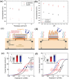
a) Overpotential versus thickness at 1 mA cm−2 (hollow circles) and 10 mA cm−2 (filled circles) for α‐FeOOH and Co‐Bi in 1 m Na2CO3. b) Overpotential versus pH at 1 mA cm−2 (black circles) and 10 mA cm−2 (red circles) for α‐FeOOH and Co‐Bi in 1 m Na2CO3. Reproduced with permission.101 Copyright 2014, American Chemical Society. Schematics of the c) planar and d) 3D nanostructured cocatalysts deposited onto a photoelectrode. The PEC J–V curves of a photoelectrode with e) planar and f) 3D‐structured cocatalysts. A cat indicates the proportion of the metal cocatalysts on the whole surface of a photoelectrode. A 3D is the increased surface area of the 3D catalyst structure with the given A cat. ηhalf‑STH is the half cell solar‐to‐hydrogen efficiency. As for traditional planar cocatalysts, an optimum A cat exists for the maximum PEC performance. By contrast, a photoelectrode with the 3D structured cocatalysts can achieve the ultimate PEC performance of the semiconductor and cocatalyst materials. Reproduced with permission.245 Copyright 2017, American Chemical Society.

References

    1. Zhang N., Han C., Fu X., Xu Y.‐J., Chem 2018, 4, 1832.
    1. Chen X., Li N., Kong Z., Ong W., Zhao X., Mater. Horiz. 2018, 5, 9.
    1. Huang X., Wang J., Li T., Wang J., Xu M., Yu W., Abed A. E., Zhang X., Beilstein J. Nanotechnol. 2018, 9, 30. - PMC - PubMed
    1. Alfaifi B. Y., Ullah H., Alfaifi S., Tahir A. A., Mallick T. K., Veruscript Funct. Nanomater. 2018, 2, BDJOC3.
    1. Rajeshwar K., J. Appl. Electrochem. 1995, 25, 1067.

LinkOut - more resources