Review
. 2019 Jan 28;12(3):407.
doi: 10.3390/ma12030407.

Corrosion of Metallic Biomaterials: A Review

Affiliations
Review

Corrosion of Metallic Biomaterials: A Review

Noam Eliaz. Materials (Basel). .

Abstract

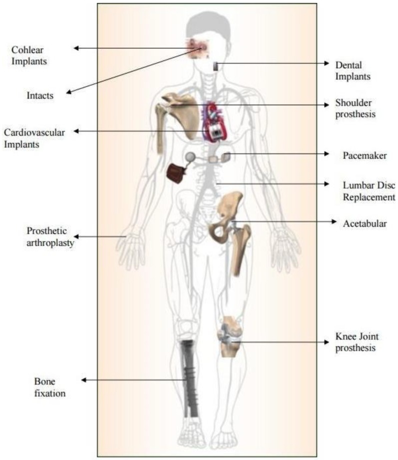
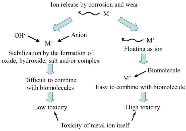
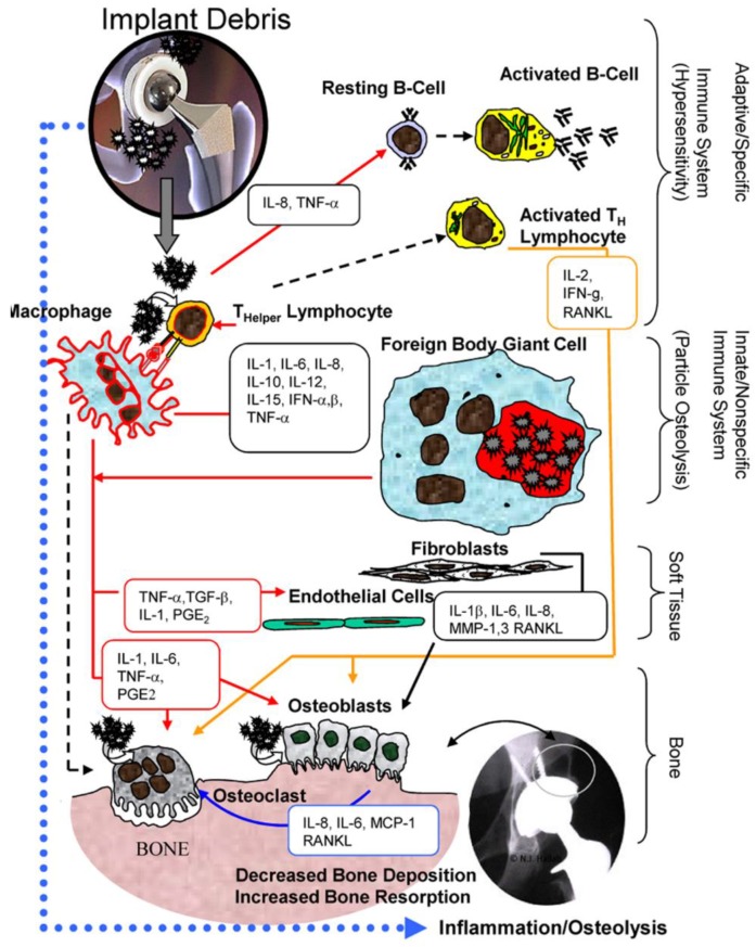
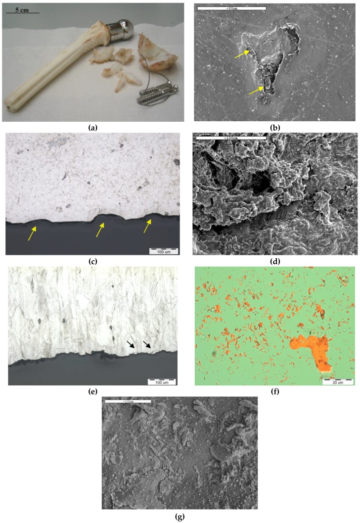
Metallic biomaterials are used in medical devices in humans more than any other family of materials. The corrosion resistance of an implant material affects its functionality and durability and is a prime factor governing biocompatibility. The fundamental paradigm of metallic biomaterials, except biodegradable metals, has been "the more corrosion resistant, the more biocompatible." The body environment is harsh and raises several challenges with respect to corrosion control. In this invited review paper, the body environment is analysed in detail and the possible effects of the corrosion of different biomaterials on biocompatibility are discussed. Then, the kinetics of corrosion, passivity, its breakdown and regeneration in vivo are conferred. Next, the mostly used metallic biomaterials and their corrosion performance are reviewed. These biomaterials include stainless steels, cobalt-chromium alloys, titanium and its alloys, Nitinol shape memory alloy, dental amalgams, gold, metallic glasses and biodegradable metals. Then, the principles of implant failure, retrieval and failure analysis are highlighted, followed by description of the most common corrosion processes in vivo. Finally, approaches to control the corrosion of metallic biomaterials are highlighted.

Keywords: biocompatibility; biodegradable metals; biomaterials; body environment; corrosion; failure; metallic glasses; shape memory alloys; stainless steels; titanium alloys.


Conflict of interest statement

The author declares no conflict of interest.

Figures

Figure 1
Figure 1
Application of metallic biomaterials as implants in different areas of the human body [39]. Reproduced with permission from Bentham Science Publishers.
Figure 2
Figure 2
Two possible toxicity routes for metal ions released into body fluids due to corrosion and wear [42]. Reprinted with permission from Springer Nature.
Figure 3
Figure 3
The biologic reactivity of implant debris causes local immune responses primarily mediated by macrophages, which produce reactive oxygen intermediates and pro-inflammatory cytokines that affect a host of local cell types and induce a widening zone of soft-tissue damage and inflammation [69]. Reprinted with permission from Springer Nature.
Figure 4
Figure 4
The use of Bio-Ferrography in the study of biodegradation of artificial hip joint. (a) A retrieved cementless isoelastic hip joint. (b,c) SEM and optical microscope images of pits on the neck surface. (d,e) Transgranular SCC of a stainless steel screw. (f,g) Isolated 316L stainless steel particles as seen under an optical microscope with bichromatic illumination (f) and by SEM (f).
Figure 5
Figure 5
Comparison between typical wear particle sizes versus wear rates reported for various acetabular liners used in total hip replacement (THR). Data is presented based on the volumetric wear rate (a) and wear particle generation rate (b) [118]. Reprinted with permission from John Wiley & Sons, Inc.
Figure 6
Figure 6
Schematics of cyclic potentiodynamic polarization curves of: (a) a metal that exhibits a protection potential, (b) a metal that does not exhibit a protection potential and (c) a metal that repassivates.
Figure 7
Figure 7
Comparison between potentiostatic (dashed line) and galvanostatic (bold line) anodic polarization curves. The x-axis is in logarithmic scale.
Figure 8
Figure 8
Polarization curves for some biomaterials. Reprinted from Greener et al. [125].
Figure 9
Figure 9
Regeneration time of surface oxide films on biomaterials. Drawn based on values from Hanawa [126].
Figure 10
Figure 10
The potential-pH diagram for iron at 37 °C and wet (hydrous) corrosion products. The lines for two concentrations (10–6 M and 1 M) of soluble species are drawn.
Figure 11
Figure 11
Comparison between selected corrosion resistance characteristics of several stainless steels in Hank’s solution, illustrating the effect of nitrogen concentration in the steel [37]. Reproduced with permission from De Gruyter.
Figure 12
Figure 12
Pourbaix diagram of the Ti–H2O system at 25 °C: (a) not taking into account titanium hydrides and (b) taking into account titanium hydrides. Line numbers correspond to reaction numbers in Ref. [186]. Solid lines bound the stability regions of the solid phases in equilibrium with 10–6, 10–4, 10–2 and 100 M activity values of the soluble titanium species. Fine broken lines mark equilibria between the dissolved species. (c) and (d) are the corresponding Pourbaix diagrams for (a) and (b), respectively, when marking only the immunity, passivation and corrosion domains [186]. Reprinted with permission of Elsevier.
Figure 13
Figure 13
(a) OCP versus time and (b) cyclic potentiodynamic polarization curves of 316L stainless steel, Co-Ni-Cr-Mo alloy, CP-Ti, Ti–6Al–4V alloy and IMI 834 T-based alloy. Tests were conducted in deaerated Hank’s solution at 37 °C [185]. Reprinted with permission of Elsevier.
Figure 14
Figure 14
The time dependence of the OCP in saline solution at pH 5.5, T = 37 °C, of CP-Ti as well as of Ti-5Ag and Ti-5Ag-35Sn alloys processed by three-dimensional printing [187]. Reprinted with permission from Elsevier.
Figure 15
Figure 15
Potentiodynamic polarization curves in saline solution at pH 5.5, T = 37 °C, of pure Ti as well as of Ti–5Ag and Ti–5Ag–35Sn alloys processed by three-dimensional printing [187]. Reprinted with permission from Elsevier.
Figure 16
Figure 16
Stress–strain–temperature diagram of SMAs, illustrating both the shape memory and superelasticity phenomena [203]. Reprinted with permission from MDPI AG.
Figure 17
Figure 17
Ashby diagram comparing the mechanical properties of conventional bioglasses, biometals and the novel biomedical BMGs [224]. Reprinted with permission from Elsevier.
Figure 18
Figure 18
Medical devices made out of BMGs. (a) Commercial martensitic steel surgical blade coated with ZrCuAlAgSi BMG film (left) and ZrCuAlAgSi BMG surgical blade (right). (b) The ezlase diode dental laser system, from Biolase Technology, uses a glassy metal in its housing. (c) BMG medical stapling anvils. (d) Amorphous alloys in minimally invasive medical devices [224]. Reprinted with permission from Elsevier.
Figure 19
Figure 19
Radiographs revealing the fractures in vivo of cementless femoral stems in three humans (ac) represent cases 1, 2 and 6, respectively, in Table I in Ref. [266]). The failures were initiated by a fretting fatigue mechanism and propagated via pure bending fatigue [266]. Reprinted with permission from Wolters Kluwer Health, Inc.
Figure 20
Figure 20
Types of corrosion in common implants [39]. Reprinted with permission from Bentham Science Publishers.
Figure 21
Figure 21
Crevice corrosion in a screw hole in fracture fixation plate [2]. Reprinted with permission from Elsevier.
Figure 22
Figure 22
Pitting corrosion. (a) An oxidized tubing Nitinol stent after six months implantation into the iliac artery of a minipig [283]. (b) A Mg–Y–Ca–Zr WX11 alloy in the as-cast condition following potentiodynamic polarization test in DMEM with 10% FBS at 37 °C and cleaning with CrO3/AgNO3 solution [284]. (b) also shows corrosion at prone grain boundary regions (arrow). Reprinted with permission from Elsevier.
Figure 23
Figure 23
(a) Indexing of corroded grain boundaries based on orientational image mappings (OIM) established by electron backscatter diffraction (EBSD). (b) Indexing of uncorroded grain boundaries based on OIM (overlaid). “G” indicates general grain boundary geometry with no lattice site coincidence, “LA” indicates low angle [287]. Reprinted with permission from John Wiley & Sons, Inc.
Figure 24
Figure 24
Comparison of elemental mapping of the cross-sections of cylindrical Mg–Ca specimens, which were implanted in the subchondral bone of rat femoral condyle, at (a) 3 days, (b) 2 weeks, and (c) 8 weeks post-implantation. (a–c) Cross-sectional SEM images acquired by a BSE detector. EDS elemental maps show the distributions of Mg (a1–c1), Ca (a2–c2) and O (a3–c3). The white dotted arrows direct to Mg-depletion traces (a1) and Ca-rich lines (a2) between primary Mg particles and the lamellar structures. The in vivo corrosion is macroscopically governed by the interdiffusion of Ca and O along the three-dimensional lamellar network and by the simultaneous surface diffusion of the primary Mg phase [292]. Reprinted with permission from John Wiley & Sons, Inc.
Figure 25
Figure 25
A galvanic series of various metals and alloys in flowing seawater at 2.4 to 4.0 m s–1 for 5 to 15 days at 5 to 30 °C. Dark boxes indicate active behaviour of active-passive alloys. Values of top axis: volts versus SCE. Source: ASTM G82–98(2014) [295].
Figure 26
Figure 26
SEM fractographs of various Mg biomaterials that fractured by SCC in different solutions. (a,b) represent crack propagation by an anodic dissolution mechanism in in NaCl + K2CrO4 solution; the rates of film rupture and regrowth compete. (a) IGSCC, (b) TGSCC of Mg–Al alloy. (c) through (h) represent crack propagation by a mixed-mode mechanism. (c) IGSCC of ZE41 in NaCl. The IGSCC is associated with second-phase particles along grain boundaries. (d) TGSCC of QE22 in NaCl. The TGSCC fracture path is consistent with a mechanism involving hydrogen. (e,f) TGSCC of ZX50 and WZ21 in modified simulated body fluid (m-SBF), respectively. The electrochemical breakdown or mechanical rupture of the protective film resulted in entry of hydrogen into the alloy matrix and subsequent embrittlement. (g) IGSCC of WE43 in m-SBF. The intergranular cracking (IGC) is associated with electrochemical dissolution along the grain boundaries. (h) IGSCC and TGSCC of EV31A in NaCl. While the IGC is due to the presence of bulky precipitates at grain boundaries, the transgranular cracking (TGC) is due to hydrogen entry into the matrix. (I,j) represent hydrogen-assisted cracking mechanism. (i) TGSCC of Mg–Mn in NaCl. TGSCC with the evidence of flat parallel facets is an indication of the hydrogen-assisted cracking. (j) TGSCC of AZ91D in m-SBF. Fracture of protective films at the crack surface allows hydrogen to diffuse into the alloy matrix [307]. Reprinted with permission from Springer Nature.
Figure 27
Figure 27
Top view of the fitted fractured mates of a stainless steel plate after ultrasonic cleaning [327]. Reprinted with permission from Elsevier.
Figure 28
Figure 28
Top: S-N fatigue curves for E325 and E400 Mg alloys tested in air and m-SBF. Arrows correspond to run-out samples. Bottom: SEM fractographs: (a) E325 tested in air, (b) E325 tested in m-SBF, (c) E400 tested in air, (d) E400 tested in m-SBF. σmax is the maximum applied stress amplitude and Nf is the number of cycles to failure. The arrows in bi and di indicate locations of crack nucleation [324]. Reprinted with permission from Elsevier.
Figure 29
Figure 29
Schematics of the mechanics of fretting [40]. (a) Elastic bending strains under an applied bending moment, M, in conjunction with rigidly bound contact point (triangles) can give rise to elastically-based displacements, Δ, in the taper. (b) Zoom-in of elastic fretting strains with the displacement being dependent on the bending stress, elastic modulus and distance from the rigid contact. (c) Schematic of a zoom-in onto the contact region within a modular taper. Crevice solution can creep to the contacts and the interface will consist of asperity-asperity contact and both normal and frictional stresses. (d) Close-up of metal-oxide surfaces in asperity contact, causing contact stresses, local surface deformation and oxide debris generation [40]. Reprinted with permission from Springer Nature.
Figure 30
Figure 30
Schematics of asperity-oxide-metal interfaces showing some of the factors associated with fretting corrosion processes [40]. (a) The surface oxide film in contact with an opposing asperity has a structure that typically consists of an oxide dome on an oxide film with its characteristic modulus of elasticity, fracture strain and residual stresses. A lattice mismatch between oxide and metal gives rise to residual stresses and interfacial stresses as does the asperity interaction. The metal substrate structure and chemistry are also important, for example, the dislocation density. (b) An asperity moving across a metal-oxide surface where contact stresses and motion scrape oxide from the metal surface, generating oxide debris. Behind the moving asperity, electrochemical reactions regenerate the oxide and dissolve metal cations into the crevice solution. Hydrogen ion generation and anions migrating into the crevice to maintain charge neutrality cause local pH drop [40]. Reprinted with permission from Springer Nature.
Figure 31
Figure 31
A typical fretting corrosion current transient [350]. Reprinted with permission from MDPI AG.
Figure 32
Figure 32
Evans diagrams illustrating the change in potential and current due to (a) the oxide covered Ti surface, and (b) the increase in fretting area/time. Dashed lines represent the changes occurring as the cathode area decreases with the progress in fretting [346]. Reprinted with permission of Elsevier.
Figure 33
Figure 33
(a) The metal taper of a retrieved hip implant revealing pitting corrosion (marked in white circles) initiated preferentially in a crevice formed due to fretting abrasion (5–40 μm scratches). This damage was imaged midway between proximal and distal ends on the taper. (b)A different component showing scratches (50–500 μm) throughout head taper, with preferential pitting inside the scratches, imaged midway between the proximal and distal ends on the taper. Corrosion by-products (biological and electrochemical deposits) accumulated inside the scratches [353]. Reprinted with permission of Elsevier.
Figure 34
Figure 34
DLC-coated artificial joints. (a) Talar and (b) tibial components of an ankle joint, both made from a nitrided AISI Z5 CNMD 21 steel and coated with DLC. Manufacturer: Matériels Implants du Limousin SA (M.I.L.SA.) [360]. Reprinted with permission of Elsevier. (c) Diamolith™ (DLC)-coated acetabular cup in a hip joint. Diamolith™ is deposited by Plasma Enhanced Chemical Vapour Deposition (PECVD). It is deposited by a vacuum-based process where precursor gases are introduced into the process chamber and are broken down within the ionized plasma into various species of carbon, hydrogen and other dopants that are subsequently condensed as a solid entity onto the substrate surface. Source: http://www.dpaonthenet.net/article/55077/Diamond-like-coatings-service-prolongs-tool-and-component-life.aspx.
Figure 35
Figure 35
A miniature glaucoma implant (Ex-PRESS™, Optonol Ltd.) made of 316LVM steel. (a) A close-up after mechanical grinding, and (b) A device after novel electropolishing [369]. Reprinted with permission of John Wiley and Sons.

Similar articles

Cited by

References

    1. Williams D.F., Black J., Doherty P.J. Consensus report of second conference on definitions in biomaterials. In: Doherty P.J., Williams R.L., Williams D.F., Lee A.J.C., editors. Biomaterial-Tissue Interfaces. Volume 10. Elsevier; Amsterdam, The Netherlands: 1992. pp. 525–533.
    1. Ratner B.D., Hoffman A.S., Schoen F.J., Lemons J.E., editors. Biomaterials Science: An Introduction to Materials in Medicine. 2nd ed. Academic Press; San Diego, CA, USA: 2004.
    1. Williams D.F., editor. Definitions in Biomaterials—Proceedings of a Consensus Conference of the European Society Biomaterials. Volume 4 Elsevier; New York, NY, USA: 1987.
    1. Bronzino J.D., Peterson D.R., editors. The Biomedical Engineering Handbook. 4th ed. CRC Press; Boca Raton, FL, USA: 2015.
    1. Zierold A.A. Reaction of bone to various metals. Arch. Surg. 1924;9:365–412. doi: 10.1001/archsurg.1924.01120080133008. - DOI

LinkOut - more resources