. 2019 Jan 18:14:733-751.
doi: 10.2147/IJN.S187664. eCollection 2019.

Enhanced bone regeneration of the silk fibroin electrospun scaffolds through the modification of the graphene oxide functionalized by BMP-2 peptide

Affiliations

Enhanced bone regeneration of the silk fibroin electrospun scaffolds through the modification of the graphene oxide functionalized by BMP-2 peptide

Jiannan Wu et al. Int J Nanomedicine. .

Abstract

Introduction: Bone tissue engineering has become one of the most effective methods to treat bone defects. Silk fibroin (SF) is a natural protein with no physiological activities, which has features such as good biocompatibility and easy processing and causes minimal inflammatory reactions in the body. Scaffolds prepared by electrospinning SF can be used in bone tissue regeneration and repair. Graphene oxide (GO) is rich in functional groups, has good biocompatibility, and promotes osteogenic differentiation of stem cells, while bone morphogenetic protein-2 (BMP-2) polypeptide has an advantage in promoting osteogenesis induction. In this study, we attempted to graft BMP-2 polypeptide onto GO and then bonded the functionalized GO onto SF electrospun scaffolds through electrostatic interactions. The main purpose of this study was to further improve the biocompatibility of SF electrospun scaffolds, which could promote the osteogenic differentiation of bone marrow mesenchymal stem cells and the repair of bone tissue defects.

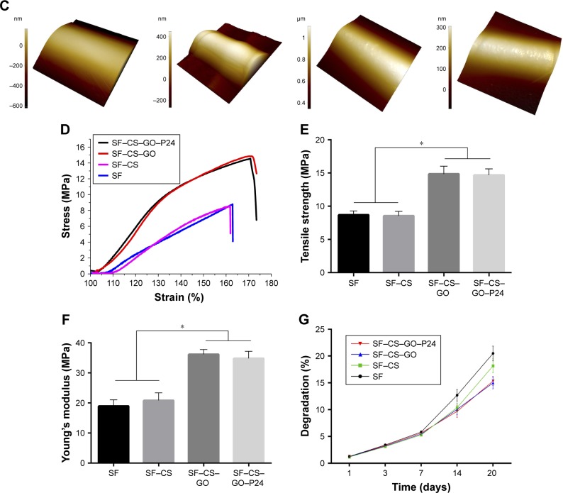
Materials and methods: The successful synthesis of GO and functionalized GO was confirmed by transmission electron microscope, X-ray photoelectron spectroscopy, and thermogravimetric analysis. Scanning electron microscopy, atomic force microscopy, mechanical test, and degradation experiment confirmed the preparation of SF electrospun scaffolds and the immobilization of GO on the fibers. In vitro experiment was used to verify the biocompatibility of the composite scaffolds, and in vivo experiment was used to prove the repairing ability of the composite scaffolds for bone defects.

Results: We successfully fabricated the composite scaffolds, which enhanced biocompatibility, not only promoting cell adhesion and proliferation but also greatly enhancing in vitro osteogenic differentiation of bone marrow stromal cells using either an osteogenic or non-osteogenic medium. Furthermore, transplantation of the composite scaffolds significantly promoted in vivo bone formation in critical-sized calvarial bone defects.

Conclusion: These findings suggested that the incorporation of BMP-2 polypeptide-functionalized GO into chitosan-coated SF electrospun scaffolds was a viable strategy for fabricating excellent scaffolds that enhance the regeneration of bone defects.

Keywords: bone marrow mesenchymal stem cells; bone morphogenetic protein-2; bone regeneration; electrospinning scaffold; graphene oxide; osteogenic differentiation; peptide; silk fibroin.


Conflict of interest statement

Disclosure The authors report no conflicts of interest in this work.

Figures

Figure 1
Figure 1
Morphology of GO. Notes: (A) TEM images of GO and GO–P24. (B) Tapping mode AFM images and height profiles of GO and GO–P24.
Figure 2
Figure 2
Surface characterization of the GO. Notes: (A) FTIR spectrum of GO, P24, and GO–P24. (B) XPS spectrum of GO and the GO–P24. (C) Quantification of atomic chemical composition of GO and GO–P24. High-resolution XPS spectra of (D) C 1s (E) N 1s peaks of GO and GO–P24. Abbreviations: GO, graphene oxide; FTIR, Fourier transform infrared spectroscopy; XPS, X-ray photoelectron spectroscopy; BE, binding energy.
Figure 3
Figure 3
Characterization of electrospun scaffolds. Notes: (A) The overall view images of the SF, SF–CS, SF–CS–GO and SF–CS–GO–P24 electrospun scaffolds. (B) SEM micrographs of four different electrospun scaffolds. The below row (scale bars=2 µm) is the magnification of the electrospun fibers to the scaffolds on the upper row (scale bars=50 µm; red arrows: the contact boundary between the electrospun fibers; yellow arrow: the GO and GO–P24 nanosheets coated on the surface of the electrospun fibers). (C) The AFM images show the surface roughness of the four groups of the electrospun fibers. (D) Typical stress–strain curves, (E) tensile strength, and (F) Young’s modulus (n=5, *P<0.05 are differences between the indicated groups). (G) In vitro degradation curve of the composite scaffolds. Abbreviations: SF, silk fibroin; CS, chitosan; GO, graphene oxide; SEM, scanning electron microscopy; AFM, atomic force microscopy.
Figure 3
Figure 3
Characterization of electrospun scaffolds. Notes: (A) The overall view images of the SF, SF–CS, SF–CS–GO and SF–CS–GO–P24 electrospun scaffolds. (B) SEM micrographs of four different electrospun scaffolds. The below row (scale bars=2 µm) is the magnification of the electrospun fibers to the scaffolds on the upper row (scale bars=50 µm; red arrows: the contact boundary between the electrospun fibers; yellow arrow: the GO and GO–P24 nanosheets coated on the surface of the electrospun fibers). (C) The AFM images show the surface roughness of the four groups of the electrospun fibers. (D) Typical stress–strain curves, (E) tensile strength, and (F) Young’s modulus (n=5, *P<0.05 are differences between the indicated groups). (G) In vitro degradation curve of the composite scaffolds. Abbreviations: SF, silk fibroin; CS, chitosan; GO, graphene oxide; SEM, scanning electron microscopy; AFM, atomic force microscopy.
Figure 4
Figure 4
Biocompatibility of scaffolds. Notes: (A) Live/dead assay was used to test the cytotoxicity of the scaffolds, with living cells staining as green by Calcein-AM and dead cells staining as red by PI (scale bars=200 µm). (B) The adherence shape of BMSCs cultured on different scaffolds were observed by a confocal microscope after 24 hours (scale bars=10 µm). (C) Assessing the proliferation of BMSCs seeded onto the scaffolds after 1, 3, 5 and 7 days by CCK-8 assay (n=3, *P<0.05 as compared with other groups of scaffolds). Abbreviations: BMSC, bone marrow mesenchymal stem cell; Calcein-AM, Calcein-acetoxymethyl; CCK-8, cell counting kit-8; SF, silk fibroin; CS, chitosan; GO, graphene oxide.
Figure 5
Figure 5
(A) TGA curves of GO and GO–P24. (B) TGA curves of SF and SF–GO–P24. (C) The cumulative release curve of P24 polypeptide from GO–P24 at 37°C in PBS. (D) ALP activity of BMSCs after 7 days of culture (n=3, *P<0.05 as compared with negative control, P24 positive control, and SF–CS–GO scaffolds). Abbreviations: TGA, thermogravimetric analysis; GO, graphene oxide; SF, silk fibroin; BMSC, bone marrow mesenchymal stem cell; CS, chitosan.
Figure 6
Figure 6
Immunofluorescence staining for OPN and COL I of BMSCs cultured on the scaffolds under common medium and osteogenic medium conditions (scale bars=50 µm). Abbreviations: BMSC, bone marrow mesenchymal stem cell; SF, silk fibroin; CS, chitosan; GO, graphene oxide.
Figure 7
Figure 7
RT-PCR assay to test the expression of osteogenic-related genes (ALP, Runx2, OPN, and COL I) of BMSCs cultured on the scaffolds under osteogenic medium condition (n=3, *P<0.05 as compared with other groups of scaffolds). Abbreviations: RT, real time; BMSC, bone marrow mesenchymal stem cell; SF, silk fibroin; CS, chitosan; GO, graphene oxide.
Figure 8
Figure 8
Micro-CT analysis of bone formation after the scaffold implantation into critical-sized bone defects 8 weeks later. Notes: (A) Micro-CT images of the bone regeneration from the different groups of the scaffolds. The yellow dotted line shows bone regeneration in bone defect in the sagittal plane. (B and C) Quantification of the bone formation from the micro-CT images (n=5, *P<0.05 as compared with other groups of scaffolds). (D) Histological analysis using H&E and Masson trichrome staining. The red dotted line represents the defect area (scale bar=2 mm), and the blue dotted line is one side of the defect under a high magnification view (40×; scale bar=500 µm). Abbreviations: CT, computed tomography; SF, silk fibroin; CS, chitosan; GO, graphene oxide.
Figure 9
Figure 9
A brief schematic drawing of the design of this study. Abbreviations: SF, silk fibroin; CS, chitosan; GO, graphene oxide; EDC, 1-(3-dimethylaminopropyl)-3-ethylcarbodiimide hydrochloride; NHS, N-hydroxysuccinimide.

References

    1. Hutmacher DW. Scaffolds in tissue engineering bone and cartilage. Biomaterials. 2000;21(24):2529–2543. - PubMed
    1. Liu X, Ma PX, Px M. Polymeric scaffolds for bone tissue engineering. Ann Biomed Eng. 2004;32(3):477–486. - PubMed
    1. Pina S, Oliveira JM, Reis RL. Natural-based nanocomposites for bone tissue engineering and regenerative medicine: a review. Adv Mater. 2015;27(7):1143–1169. - PubMed
    1. Gomes ME, Godinho JS, Tchalamov D, Cunha AM, Reis RL. Alternative tissue engineering scaffolds based on starch: processing methodologies, morphology, degradation and mechanical properties. Mater Sci Eng C. 2002;20(1–2):19–26.
    1. Agrawal CM, Ray RB. Biodegradable polymeric scaffolds for musculo-skeletal tissue engineering. J Biomed Mater Res. 2001;55(2):141–150. - PubMed