. 2019 Jan;3(1):1-23.
doi: 10.1109/TRPMS.2018.2883437.

Advances in Computational Human Phantoms and Their Applications in Biomedical Engineering - A Topical Review

Affiliations

Advances in Computational Human Phantoms and Their Applications in Biomedical Engineering - A Topical Review

Wolfgang Kainz et al. IEEE Trans Radiat Plasma Med Sci. 2019 Jan.

Abstract

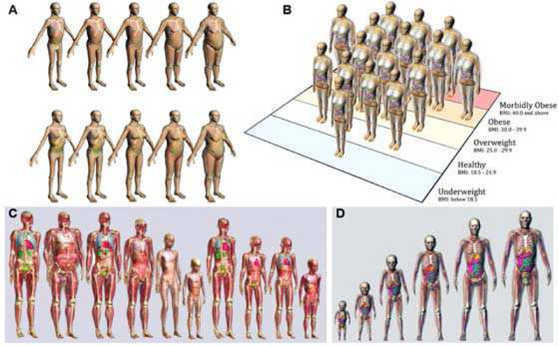
Over the past decades, significant improvements have been made in the field of computational human phantoms (CHPs) and their applications in biomedical engineering. Their sophistication has dramatically increased. The very first CHPs were composed of simple geometric volumes, e.g., cylinders and spheres, while current CHPs have a high resolution, cover a substantial range of the patient population, have high anatomical accuracy, are poseable, morphable, and are augmented with various details to perform functionalized computations. Advances in imaging techniques and semi-automated segmentation tools allow fast and personalized development of CHPs. These advances open the door to quickly develop personalized CHPs, inherently including the disease of the patient. Because many of these CHPs are increasingly providing data for regulatory submissions of various medical devices, the validity, anatomical accuracy, and availability to cover the entire patient population is of utmost importance. The article is organized into two main sections: the first section reviews the different modeling techniques used to create CHPs, whereas the second section discusses various applications of CHPs in biomedical engineering. Each topic gives an overview, a brief history, recent developments, and an outlook into the future.

Keywords: Human anatomy; computational modeling; phantoms.


Figures

Fig. 1.
Fig. 1.
A model of the left lung defined by different modeling methods; (a) The CSG-type modeling after the Boolean operation (subtraction) is performed involving two ellipsoids; (b) A voxel representation of the lung; (c) A BREP-type of modeling of the same lung using a polygon mesh [5] [6].
Fig. 2.
Fig. 2.
(a) Cardiac and respiratory motion models of the surface-based XCAT (left) and VIP-Man (right) phantoms. Transformations are applied to the surfaces to deform them. (b) 4D voxelized respiratory phantom of Han et al. [25]. Transforms are applied to the individual voxels to deform the image. Full animation of the respiratory motion and deformation can be found elsewhere (http://hurel.hanyang.ac.kr/Phantom/4DVoxel.gif)
Fig. 3.
Fig. 3.
The adult female mesh-type reference CHP implemented in Geant4 (left), MCNP6 (middle) and PHITS (right).
Fig. 4.
Fig. 4.
Thermal conductivity values taken from the IT’IS Tissue Database [61] depicted in a cross-section of a female CHP.
Fig. 5.
Fig. 5.
Example libraries of computational phantoms. Models are shown from (a) RPI, (b) UF/NCI, (c) IT’IS, and (d) the XCAT series. Only selected phantoms are shown from each population.
Fig. 6.
Fig. 6.
Boxplots comparing all organ dose percent differences for each of the six matching parameters. The vertical lines extend at most 1.5 times the interquartile range.
Fig. 7.
Fig. 7.
Dose-area histograms (DAHs) for 10 select high-dose cases normalized to peak skin dose. Ordinate indicates what fraction of peak skin dose is delivered to an area of exposed patient skin given on the abscissa.
Fig. 8.
Fig. 8.
Polygon mesh version of the ICRP 110 reference phantom with selected dimensions and the result of its adjustment to patient #1 and patient #2.
Fig. 9.
Fig. 9.
Tissue losses, i.e., absorption in a cross section of DUKE (member of ViP), and the E-field lines generated by the transmitter in the vicinity of the phone.
Fig. 10.
Fig. 10.
Induced absorption of the B1-field in DUKE (ViP) during MRI scans (right side) and the associated local tissue temperatures (left side).
Fig. 11.
Fig. 11.
Adult male and female mesh-type ICRP reference computational phantoms [180].
Fig. 12.
Fig. 12.
CT simulation using an CHP. Imaging data is acquired from the CHP using the scanner model; the data is then reconstructed into the simulated CT images.
Fig. 13.
Fig. 13.
(Top) Sample transaxial-slice CT images of the head at 80 kVp (Left) and 120 kVp (Right) showing a beam-hardening artifact (arrow). (Bottom) Sample noisy transaxial-slice abdominal CT images at 1 mAs/view (Left) and 0.1 mAs/view (Right).
Fig. 14.
Fig. 14.
Effective dose (ED) plotted as a function of patient size for CT, Tomosynthesis (Tomo), posteroanterior + left lateral radiography (PA + Left LAT), and anteroposterior radiography (AP).
Fig. 15.
Fig. 15.
Simulated myocardial SPECT images reconstructed using an iterative order-subset expectation-maximization (OS-EM) method with accurate models, i.e., the XCAT phantom, of the system response and imaging physics for significant improvement in both image quality and quantitative accuracy. From top to bottom row, OS-EM images obtained without any modeling (1st row), with the collimator-detector response (CDR) (2nd row), with CDR and attenuation (3rd row), and with CDR, attenuation and scatter modeling (4th row). From the left to right column: OS-EM with 1, 2, 3, 4, 5, 10 and 20 iterations.
Fig. 16.
Fig. 16.
Sample noise-free transaxial-slice cardiac CT images at mid-diastolic phase with fast full scan (Left) and at 333ms/rotation short scan (Right) showing the effect of motion of the coronary artery (arrows). Images were sharpened to show the artifacts more clearly.
Fig. 17.
Fig. 17.
Simulated myocardial SPECT images demonstrating the effect of respiratory motion. (Left column). Same sample short-axis slice through the center of the heart. (Right column). From the 4D XCAT phantom (Top row) without respiratory motion, and with (Middle row) 2 cm and (Bottom row) 4 cm respiratory motion amplitude showing the increasing motion artifacts on the superior and inferior wall of the myocardium.
Fig. 18.
Fig. 18.
Evaluation of a 4D PET image reconstruction method with respiratory motion (RM) compensation using the 4D XCAT phantom with respiratory motion capabilities. (a) A sample coronal slice from the 3D XCAT phantom with three lung lesions and no RM. The PET images of the same coronal slice obtained from (b) a 3D Maximum Likelihood-Expectation Maximization (ML-EM) image reconstruction algorithm with no RM compensation, (c) a 4D ML-EM image reconstruction with RM compensation using known RM modeling, and (d) a 4D ML-EM image reconstruction with RM compensation using an estimated 4D RM model.

References

    1. Agostinelli S et al., “Geant4—a simulation toolkit,” Nucl. Instr. Meth. Phys. Res. Sec. A, vol. 506, no. 3, pp. 250–303, July 2003.
    1. Leyton M, A generative theory of shape, vol. 2145, Berlin: Springer-Verlag, November 2001.
    1. Stroud I, “Boundary representation modeling techniques”, London: Springer-Verlag, July 2006.
    1. Cristy M and Eckerman KF, “Specific absorbed fractions of energy at various ages from internal photon sources, Part I: Methods,” Oak Ridge National Laboratory, Oak Ridge, TN, USA, 1987.
    1. Xu XG and Eckerman KF, “Handbook of anatomical models for radiation dosimetry”, Taylor & Francis, 2009.

LinkOut - more resources