. 2019 Mar 13;19(6):1013-1026.
doi: 10.1039/c8lc00957k.

Two-way communication between ex vivo tissues on a microfluidic chip: application to tumor-lymph node interaction

Affiliations

Two-way communication between ex vivo tissues on a microfluidic chip: application to tumor-lymph node interaction

Sangjo Shim et al. Lab Chip. .

Abstract

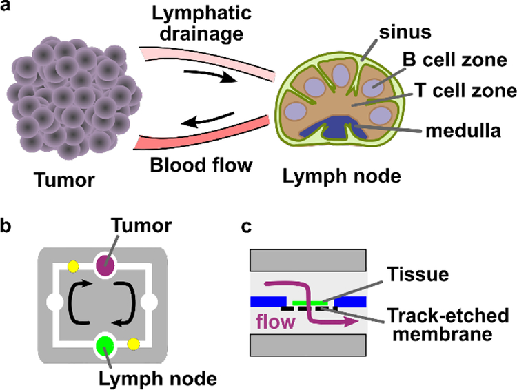
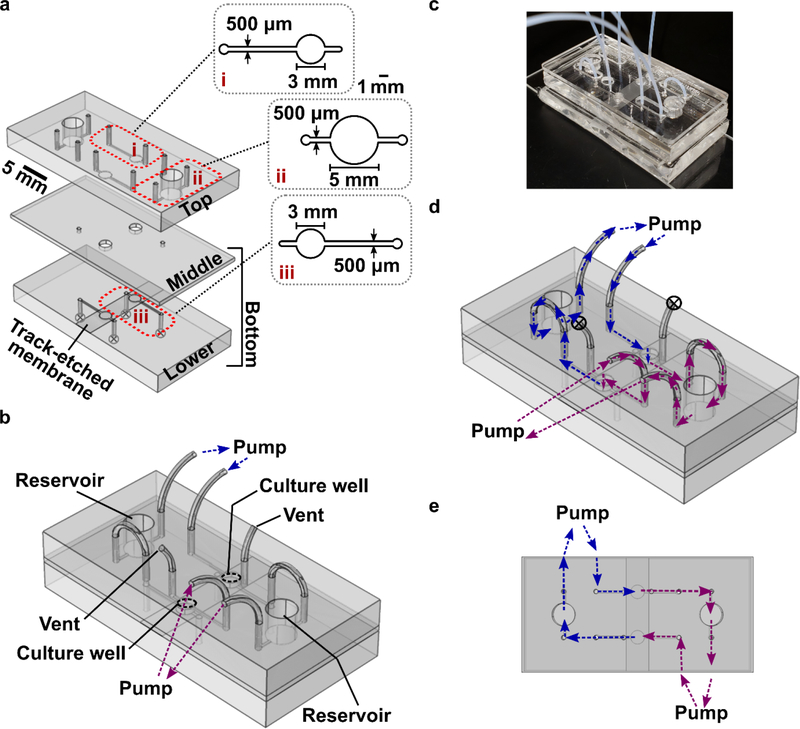
Experimentally accessible tools to replicate the complex biological events of in vivo organs offer the potential to reveal mechanisms of disease and potential routes to therapy. In particular, models of inter-organ communication are emerging as the next essential step towards creating a body-on-a-chip, and may be particularly useful for poorly understood processes such as tumor immunity. In this paper, we report the first multi-compartment microfluidic chip that continuously recirculates a small volume of media through two ex vivo tissue samples to support inter-organ cross-talk via secreted factors. To test on-chip communication, protein release and capture were quantified using well-defined artificial tissue samples and model proteins. Proteins released by one sample were transferred to the downstream reservoir and detectable in the downstream sample. Next, the chip was applied to model the communication between a tumor and a lymph node, to test whether on-chip dual-organ culture could recreate key features of tumor-induced immune suppression. Slices of murine lymph node were co-cultured with tumor or healthy tissue on-chip with recirculating media, then tested for their ability to respond to T cell stimulation. Interestingly, lymph node slices co-cultured with tumor slices appeared more immunosuppressed than those co-cultured with healthy tissue, suggesting that the chip may successfully model some features of tumor-immune interaction. In conclusion, this new microfluidic system provides on-chip co-culture of pairs of tissue slices under continuous recirculating flow, and has the potential to model complex inter-organ communication ex vivo with full experimental accessibility of the tissues and their media.


Conflict of interest statement

CONFLICT OF INTEREST STATEMENT

The authors have no conflicts of interest to declare.

Figures

Figure 1.
Figure 1.
Modeling tumor-lymph node interactions on a dual-slice microfluidic chip with continuous recirculating flow. (a) In vivo, tumors and lymph nodes communicate via lymphatic fluid drainage from the tumor to lymph node, and via blood flow that carries signals and cells from the lymph node back to the tumor. (b, c) A simplified conceptual schematic (b, top view; c, side view of tissue chamber) of the dual-slice chip. Arrows indicate the direction of fluid flow. The tissue sample rests on a track-etched membrane, and flow passes through it on the way to the next chamber.
Figure 2.
Figure 2.
Device fabrication and operation. (a) 3D rendering of the three layers of the device, drawn to scale. The top and lower layers were made of PDMS with 200-μm feature depth, and the middle layer was a 1-mm thick PDMS membrane. A 10-μm thick track-etched polycarbonate membrane, shown atop the lower layer, was fixed in place using PDMS glue. Insets show enlarged diagrams of (i) the top portion of a culture well, and (ii) a reservoir, and (iii) the lower portion of a culture well, located below the polycarbonate membrane. (b) 3D schematic of the assembled device with tubing inserted into the access ports. The culture wells, reservoirs, connections for peristaltic pumps, and air vents are labelled. (c) Photo of the assembled device, shown without binder clips for clarity. A rigid polymethyl methacrylate (PMMA) cover is placed over the top PDMS layer for mechanical support; the cover was omitted in panels a-b for clarity. (d) The flow path for recirculating fluid flow, overlaid onto the same schematic as in (b). The two colors (blue, purple) indicate flow through each half of the chip; the color changes at the point where fluid passes through the tissue in the culture well. (e) The flow path when the chip is viewed from the top, shown without tubing for clarity.
Figure 3.
Figure 3.
Design of the dual slice chip. (a) Top view schematic to illustrate the design. The chip houses two culture wells for tissue slices (green) and two open reservoirs, with two in-line peristaltic pumps (yellow circles) for recirculation of media. Black arrows indicate flow direction. (b) Cutaway schematic, drawn to scale, of the assembled device viewed along the dot-dash line shown in (a). The device is shown loaded with a tissue sample (green) and filled with media (light blue). The degassing vents are shown closed (circled x). Enlarged views below show the inlet, the culture well, and the outlet for one culture well from left to right, respectively, not to scale. Arrows denote fluid flow. The device enabled two-way communication between slices by transporting proteins released (blue arrows) by one tissue for capture (red arrows) by the next tissue. (c) Results of 3D simulation of fluid flow through a single culture well containing a tissue slice atop a track-etched membrane. Red arrows show the predicted flow direction and magnitude at each location, indicating that flow passes transversely through the slice. (d) Velocity magnitude and (e) shear stress were measured along three scan lines, placed at the top (i), middle (ii), and bottom (iii) of the tissue slice, as indicated by blue arrows in panel (c).
Figure 4.
Figure 4.
Protein release from and capture in agarose slices on a chip. (a) Avidin-HRP (red, av-HRP) was pre-soaked into an agarose slice and perfused. (b) After 2 hours, an aliquot was collected from the downstream reservoir. (c) The quantity released was similar in a microwell plate as on the chip, as quantified by reaction with a colorimetric substrate for HRP (TMB substrate) (N = 4). (d) NRho (red) was flowed on-chip through an agarose slice (green) prepared with or without biotin-functionalized beads (black dots). (e) After two hours, captured protein was visualized by fluorescence microscopy. (f) A high fluorescent intensity was observed in slices with beads but not without beads, showing specific protein capture (N = 3). Bars show mean and standard deviation. Each dot indicates one trial of the experiment. NS indicates no significant difference and * indicates p-value < 0.05, as determined by one-way ANOVA. The chip schematics were not drawn to scale.
Figure 5.
Figure 5.
Demonstrating dual-slice protein communication. (a) Experimental setup: one slice was presoaked in NRho (red dot in schematic) and the other was loaded with biotinylated beads (green dot in schematic). Initially, the protein-loaded slice showed strong but diffusing red color under fluorescent microscopy (top image), and the bead-laden slice appeared dark (lower image). (b) Quantification of fluorescent intensity at t = 0. (c) Results after 24 hours continuous perfusion: the presoaked proteins were undetectable in the first slice (top fluorescent image) and had been captured by the other, bead-laden slice (lower image) (d) Quantification of fluorescent intensity at t = 24 hours. Comparing b and d, most of the protein was transferred between the two slices. Bars show mean and standard deviation; n = 4. **** indicates p-value < 0.0001 by one-way ANOVA. The chip schematics were not drawn to scale.
Figure 6.
Figure 6.
Tumor-lymph node co-culture on the dual-slice microfluidic chip models T cell immunosuppression in draining lymph nodes. (a) On day 7 after injection of red-fluorescent 4T1 tumor cells, the tumor, TDLN, and NDLN were collected, sliced, and imaged or placed into culture. Regions of bright red fluorescence (above threshold, shown in red outlines) were selected, and (b) their integrated density (area × intensity) was quantified. Fluorescent signal was high in tumor samples, and equally low among TDLN, LDLN, and Naïve LN. (c) In an assay of stimulated IFN-γ secretion, LN slices from tumor-bearing mice showed immunosuppression in both TDLN and NDLN compared to Naïve LN. IFN-γ concentration in the culture supernatant was normalized to the area (mm2) of the LN slice. (d) Co-culture of NDLN slices with tumor slices (T-NDLN) on the dual-slice microfluidic chip induced further immunosuppression in the NDLN compared to co-culture with sections of fat pad (F-NDLN). The data was analyzed by one-way ANOVA. * and **** indicate p-value < 0.05 and < 0.0001 respectively.

References

    1. Duncombe TA, Tentori AM and Herr AE, Microfluidics: reframing biological enquiry, Nat. Rev. Mol. Cell Biol, 2015, 16, 554–567. - PMC - PubMed
    1. Sivagnanam V and Gijs MAM, Exploring Living Multicellular Organisms, Organs, and Tissues Using Microfluidic Systems, Chem. Rev, 2013, 113, 3214–3247. - PubMed
    1. Kim C, Kasuya J, Jeon J, Chung S and Kamm RD, A Quantitative Microfluidic Angiogenesis Screen for Studying Anti-Angiogenic Therapeutic Assay, Lab. Chip, 2015, 15, 301–310. - PMC - PubMed
    1. Li R, Hebert JD, Lee TA, Xing H, Boussommier-Calleja A, Hynes RO, Lauffenburger DA and Kamm RD, Macrophage-secreted TNFα and TGFβ1 influence migration speed and persistence of cancer cells in 3D tissue culture via independent pathways, Cancer Res, 2016, canres-0442. - PMC - PubMed
    1. Bhatia SN and Ingber DE, Microfluidic organs-on-chips, Nat. Biotechnol, 2014, 32, 760. - PubMed

Publication types