Review
. 2019 Feb 10;12(3):522.
doi: 10.3390/ma12030522.

Ultrasonic Vibration Assisted Electro-Discharge Machining (EDM)-An Overview

Affiliations
Review

Ultrasonic Vibration Assisted Electro-Discharge Machining (EDM)-An Overview

Nurbol Sabyrov et al. Materials (Basel). .

Abstract

Many of the industrial processes, including material removal operation for shape generation on the surface of material, exploit the assistance of ultrasonic vibrations. This trend of using ultrasonic vibration in order to improve the process performance is becoming more and more prominent recently. One of the significant applications of this ultrasonic vibration is in the industrial processes such as Electro-discharge machining (EDM), where ultrasonic vibration (UV) is inserted as a medium for enhancing the process performance. Mostly ultrasonic vibration is applied along with the EDM process to increase the efficiency of the process through debris cleansing from the sparking gap. There have been significant changes in ultrasonic assisted technology during the past years. Due to its inherent advantages, ultrasonic assistance infiltrated in different areas of EDM, such as wire cut EDM, micro EDM and die sinking EDM. This article presents an overview of ultrasonic vibration applications in electric discharge machining. This review provides information about modes of UV application, impacts on parameters of performance, optimization and process designing on difficult-to-cut materials. On the bases of available research works on ultrasonic vibration assisted EDM, current challenges and future research direction to improve the process capabilities are identified. Literature suggested improved material removal rate (MRR), increased surface roughness (SR) and tool wear ratio (TWR) due to the application of ultrasonic vibration assisted EDM. However, tool wear and surface roughness can be lessened with the addition of carbon nanofiber along with ultrasonic vibration. Moreover, the application of ultrasonic vibration to both tool and workpiece results in higher MRR compared to its application to single electrode.

Keywords: EDM; hard to cut materials; material removal rate; surface roughness; ultrasonic vibration.


Conflict of interest statement

The authors declare no conflict of interest.

Figures

Figure 1
Figure 1
Schematic diagram of the EDM system [15]. (Adapted from [15] with permission—© 2014 Springer.
Figure 2
Figure 2
(a) Representation of sparking phenomena in EDM [18]; (Adapted from [18] with permission—© 2006 Elsevier). (b) Model of EDM gap phenomena [19] in EDM. (Adapted from [19] with permission—© 2005 Elsevier).
Figure 3
Figure 3
Principle of UV assisted EDM/micro-EDM; (a) vibration applied to tool electrode [8]; (Adapted from [8] with permission—© 2008 Elsevier). (b) vibration applied to workpiece [20] (Adapted from [20] with permission—© 2008 Elsevier).and (c) vibration applied to dielectric [21]. (Adapted from21] with permission—© 2009 Elsevier).
Figure 3
Figure 3
Principle of UV assisted EDM/micro-EDM; (a) vibration applied to tool electrode [8]; (Adapted from [8] with permission—© 2008 Elsevier). (b) vibration applied to workpiece [20] (Adapted from [20] with permission—© 2008 Elsevier).and (c) vibration applied to dielectric [21]. (Adapted from21] with permission—© 2009 Elsevier).
Figure 4
Figure 4
Schematic diagram illustrating the mechanism of ultrasonic vibration assisted EDM in gas [24]. (Adapted from [24] with permission—© 2017 Springer).
Figure 5
Figure 5
Discharge current and voltage waveforms showing pulse duration, pulse interval and ignition delay [31]. (Adapted from [31] with permission—© 2006 Elsevier).
Figure 6
Figure 6
Illustration of the crater geometry and surface roughness due to series of crater formation [31] (Adapted from [31] with permission—© 2006 Elsevier).
Figure 7
Figure 7
The strength of the molten metal drop model [32]. (Adapted from [32] with permission—© 2009 Elsevier).
Figure 8
Figure 8
(a) Ultrasonic Unit (b) Ultrasonic vibrating EDM [40]. (Adapted from [40] with permission—© 1989 Elsevier).
Figure 9
Figure 9
(a) Effect to vibration on Removal rate; (b) Residual stress [40]. (Adapted from [40] with permission—© 1989 Elsevier).
Figure 10
Figure 10
(a) Relationship between vibration frequency, removal rate and surface roughness; (b) Comparison of removal rate for each electrode; (c) Relationship between vibration frequency and surface roughness [41]. (Adapted from [41] with permission—© 2018 Elsevier).
Figure 11
Figure 11
(a) Effect of tool vibration on MRR against pulse-on time (Ti); (b) pulse-on time (Ti) [42]. (Adapted from [42] with permission—© 2007 Springer).
Figure 12
Figure 12
Effect of voltage on (a) MRR; (b) Surface roughness [45]. (Adapted from [45] with permission—© 1997 Elsevier).
Figure 13
Figure 13
(a) Typical SEM micrograph showing pure ED machined surface (I = 11 A. Ti = 1 μs); (b) ultrasonic-assisted ED machined surface (I = 11 A. Ti = 1 μs) [48]. (Adapted from [48] with permission—© 2009 Springer).
Figure 14
Figure 14
Vibratory, rotary and vibro-rotary electrodes [49]. (Adapted from [49] with permission—© 2002 Elsevier).
Figure 15
Figure 15
Typical SEM micrographs of the recast layer [53]. (Adapted from [53] with permission—© 2000 Elsevier).
Figure 16
Figure 16
(a) Current pulses with ultrasonic vibration (b); Current pulses without ultrasonic vibration [55]. (Adapted from [55] with permission—© 2018 Elsevier).
Figure 17
Figure 17
(a) Schematic diagram of the driven forces on the debris within the machining gap of the hybrid process; (b) Micrographs of machined surface obtained by the hybrid process with various levels of discharge energy [25]. (Adapted from [25] with permission—© 2014 Springer).
Figure 17
Figure 17
(a) Schematic diagram of the driven forces on the debris within the machining gap of the hybrid process; (b) Micrographs of machined surface obtained by the hybrid process with various levels of discharge energy [25]. (Adapted from [25] with permission—© 2014 Springer).
Figure 18
Figure 18
Various types of ultrasonic vibration mode and amplitude [58]. (Adapted from [58] with permission—© 2013 Elsevier).
Figure 18
Figure 18
Various types of ultrasonic vibration mode and amplitude [58]. (Adapted from [58] with permission—© 2013 Elsevier).
Figure 19
Figure 19
The effect of vibration on the adhesion process. (a) Without vibration; (b) Feeding back action and (c) With vibration [64]. (Adapted from [64] with permission—© 2018 Elsevier).
Figure 20
Figure 20
Straight micro hole machined by EDM with capacitance change and ultrasonic vibration: (a) hole entrance 117.0 µm, (b) hole exit 115.6 µm (c) Cross section of a straight micro hole machined by EDM with capacitance change and ultrasonic vibration [65]. (Adapted from [65] with permission—© 2006 Iopscience).
Figure 21
Figure 21
Illustration of inclined feeding (a) upward and (b) downward [71]. (Adapted from [71] with permission—© 2016 Elsevier).
Figure 22
Figure 22
(a) Vibration orientation and cutting direction; (b) Effect of ultrasonic vibration on the machining rate as a function of the peak current; (c) Relationship between the amplitude of wire vibration and the discharge energy [72]. (Adapted from [72] with permission—© 1997 Elsevier).
Figure 23
Figure 23
(a) Wire vibration state at different frequencies; (b) Circulation of debris ejection with vibration of the workpiece [76]. (Adapted from [76] with permission—© 2013 Elsevier).
Figure 24
Figure 24
Positioning of the wire guide and workpiece [77]. (Adapted from [77] with permission—© 2013 Elsevier).
Figure 25
Figure 25
3D micron-scale surface topology of experimental results using three different methods at the same machining parameters (pulse-on time 5 μs, pulse-off time 5 μs, peak current 9A) [79]. (Adapted from [79] with permission—© 2018 Elsevier).
Figure 26
Figure 26
Comparison on relative stability index of various types of EDM; (b) Material removal rate affected by various rotation speeds with and without ultrasonic assistance; (c) Tool wear rate affected by various rotation speeds with and without ultrasonic [80]. (Adapted from [80] with permission—© 2018 springer).
Figure 27
Figure 27
Effect of workpiece vibration on microchannel surface quality (a) without vibration and (b) with vibration of 160 Hz [84]. (Adapted from [84] with permission—© 2018 Taylor & Francis).
Figure 28
Figure 28
(a) Effect of dielectric fluid and vibration on MRR and TWR (vibration amplitude = 6.4 µm); (b,c) SEM images of machined surfaces [86].
Figure 29
Figure 29
Effect of amplitude on MRR and TWR in oil dielectric machining [86].
Figure 30
Figure 30
(a) Principle of UEDM in gas (b) The effect of amplitude of ultrasonic vibration on MRR. (c) The effect of discharge current on MRR [30]. (Adapted from [30] with permission—© 2004 Elsevier).
Figure 30
Figure 30
(a) Principle of UEDM in gas (b) The effect of amplitude of ultrasonic vibration on MRR. (c) The effect of discharge current on MRR [30]. (Adapted from [30] with permission—© 2004 Elsevier).
Figure 31
Figure 31
Schematic of Dry EDM setup with rotating magnetic field [90]. (Adapted from [90] with permission—© 2013 Springer).
Figure 32
Figure 32
Schematic of horizontal UVA-EDM setup [92]. (Adapted from [92] with permission—© 2016 Elsevier).
Figure 33
Figure 33
(a,b) SEM photographs of micro-gear-array electrodes [20]. (Adapted from [20] with permission—© 2008 Elsevier).
Figure 34
Figure 34
Image of surface (a) without rotation & vibration (b) with tool rotation (c) with rotation & vibration machined surface by micro-EDM [95]. (Adapted from [95] with permission—© 2006 Elsevier).
Figure 34
Figure 34
Image of surface (a) without rotation & vibration (b) with tool rotation (c) with rotation & vibration machined surface by micro-EDM [95]. (Adapted from [95] with permission—© 2006 Elsevier).
Figure 35
Figure 35
(b) Fabrication of micro-electrodes using on-machine fabricated microelectrode; (a) micro-hole of Ø 100 m, aspect ratio 5 using vibration with (Kv < 1), (b) micro-hole of Ø 75 m, aspect ratio 10 with vibration of (Kv > 1), (c) micro-hole of Ø 60 m, aspect ratio ~17 with vibration of (Kv > 1) (SEM images are taken at 30° tilt angle) [23]. (Adapted from [23] with permission—© 2012 Elsevier).
Figure 36
Figure 36
Total duration and number of arc discharges [22]. (Adapted from [22] with permission—© 2011 Elsevier).
Figure 37
Figure 37
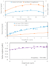
(a) The relationships between the removal rate and the ultrasonic driving voltage. (b) removal rate and different workpiece materials [96]. (Adapted from [96] with permission—© 2003 Elsevier).
Figure 38
Figure 38
(a) Comparison of material removal rate for Cu as a workpiece and brass as tool electrode for machining condition in pure dielectric fluid; (b) Machined surface image of Cu–W surface with brass as the tool electrode obtained by m-EDM processing, using MoS2 powder with ultrasonic vibration of dielectric fluid and a powder concentration of 2 g/L [21]. (Adapted from [21] with permission—© 2009 Elsevier).
Figure 39
Figure 39
(a) Ultrasonic sonotrode in micro EDM [69]; (b) Schematic diagram of the proposed hybrid micro-EDM [100]. (Adapted from [100] with permission—© 2014 Elsevier).
Figure 40
Figure 40
Schematic model for debris removal through the cavitation assisted micro-EDM of a deep micro-hole [100]. (Adapted from [100] with permission—© 2014 Elsevier).
Figure 41
Figure 41
Effect of tool vibration on MRR versus discharge current (I) for US/EDM and pure EDM [105]; (Adapted from [105] with permission—© 2008 Springer). (b) Effect of Applied voltage on MRR ((hollow circle: 15 µm amplitude; full circles: 25 µm amplitude [12]. (Adapted from [12] with permission—© 1995 Elsevier).
Figure 42
Figure 42
Effect of tool vibration on TWR versus pulse-on time (Ti) for US/EDM and pure EDM [105]. (Adapted from [105] with permission—© 2008 Springer).
Figure 43
Figure 43
(a) Effect of tool vibration on surface roughness versus pulse-on time (Ti) for US/EDM and pure EDM [105]; (Adapted from [105] with permission—© 2008 Springer). (b) Effect of ultrasonic vibration on the machined surface roughness [72]. (Adapted from [72] with permission—© 1997 Elsevier).

References

    1. Ho K., Newman S. State of the art electrical discharge machining (EDM) Int. J. Mach. Tools Manuf. 2003;43:1287–1300. doi: 10.1016/S0890-6955(03)00162-7. - DOI
    1. Leão F.N., Pashby I.R. A review on the use of environmentally-friendly dielectric fluids in electrical discharge machining. J. Mater. Process. Technol. 2004;149:341–346. doi: 10.1016/j.jmatprotec.2003.10.043. - DOI
    1. D’Urso G., Giardini C., Quarto M. Characterization of surfaces obtained by micro-EDM milling on steel and ceramic components. Int. J. Adv. Manuf. Technol. 2018;97:2077–2085. doi: 10.1007/s00170-018-1962-5. - DOI
    1. D’Urso G., Giardini C., Maccarini G., Quarto M., Ravasio C. Analysis of the surface quality of steel and ceramic materials machined by micro-EDM; Proceedings of the 18th International Conference of the European Society for Precision Engineering and Nanotechnology, EUSPEN 2018; Venice, Italy. 4–8 June 2018; pp. 431–432.
    1. Zhang J., Lee T., Wu C., Tang C. Surface integrity and modification of electro-discharge machined alumina-based ceramic composite. J. Mater. Process. Technol. 2002;123:75–79. doi: 10.1016/S0924-0136(02)00065-1. - DOI