

Mechanism of hydrogen peroxide formation by lytic polysaccharide monooxygenase
- PMID: 30746099
- PMCID: PMC6334667
- DOI: 10.1039/c8sc03980a
Mechanism of hydrogen peroxide formation by lytic polysaccharide monooxygenase
Abstract
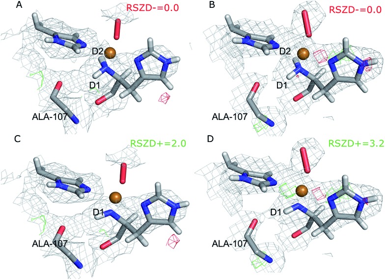
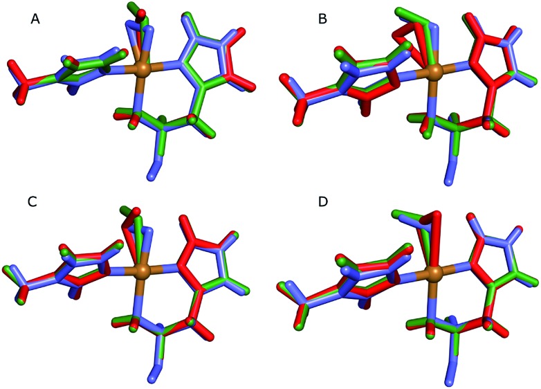
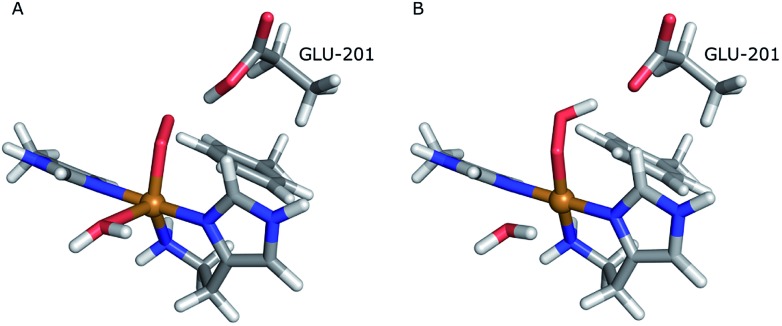
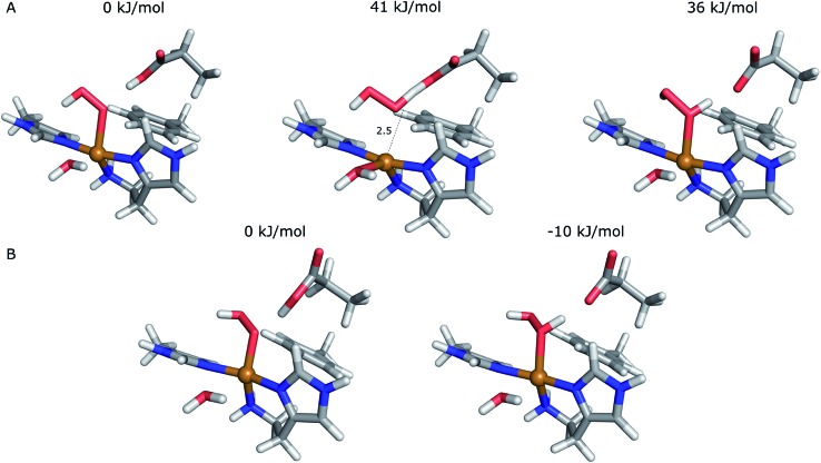
Lytic polysaccharide monooxygenases (LPMOs) are copper-containing metalloenzymes that can cleave the glycosidic link in polysaccharides. This could become crucial for production of energy-efficient biofuels from recalcitrant polysaccharides. Although LPMOs are considered oxygenases, recent investigations have shown that H2O2 can also act as a co-substrate for LPMOs. Intriguingly, LPMOs generate H2O2 in the absence of a polysaccharide substrate. Here, we elucidate a new mechanism for H2O2 generation starting from an AA10-LPMO crystal structure with an oxygen species bound, using QM/MM calculations. The reduction level and protonation state of this oxygen-bound intermediate has been unclear. However, this information is crucial to the mechanism. We therefore investigate the oxygen-bound intermediate with quantum refinement (crystallographic refinement enhanced with QM calculations), against both X-ray and neutron data. Quantum refinement calculations suggest a Cu(ii)-O-2 system in the active site of the AA10-LPMO and a neutral protonated -NH2 state for the terminal nitrogen atom, the latter in contrast to the original interpretation. Our QM/MM calculations show that H2O2 generation is possible only from a Cu(i) center and that the most favourable reaction pathway is to involve a nearby glutamate residue, adding two electrons and two protons to the Cu(ii)-O-2 system, followed by dissociation of H2O2.
Figures


References
-
- Harris P. V., Welner D., McFarland K. C., Re E., Poulsen J.-C. N., Brown K., Salbo R., Ding E., Vlasenko H., Merino S., Xu F., Cherry J., Larsen S., Leggio L. L. Biochemistry. 2010;49:3305–3316. - PubMed
-
- Vaaje-Kolstad G., Westereng B., Horn S. J., Liu Z., Zhai M., Sørlie H., Eijsink V. G. H. Science. 2010;330:219–222. - PubMed
-
- Hemsworth G. R., Davies G. J., Walton P. H. Curr. Opin. Struct. Biol. 2013;23:660–668. - PubMed
-
- Beeson W. T., Vu V. V., Span E. A., Phillips C. M., Marletta M. A. Annu. Rev. Biochem. 2015;84:923–946. - PubMed
LinkOut - more resources
Full Text Sources