

Kinetics of trifurcated electron flow in the decaheme bacterial proteins MtrC and MtrF
- PMID: 30755526
- PMCID: PMC6397555
- DOI: 10.1073/pnas.1818003116
Kinetics of trifurcated electron flow in the decaheme bacterial proteins MtrC and MtrF
Erratum in
-
Correction for Jiang et al., Kinetics of trifurcated electron flow in the decaheme bacterial proteins MtrC and MtrF.Proc Natl Acad Sci U S A. 2022 Jul 5;119(27):e2208173119. doi: 10.1073/pnas.2208173119. Epub 2022 Jun 28. Proc Natl Acad Sci U S A. 2022. PMID: 35763579 Free PMC article. No abstract available.
Abstract
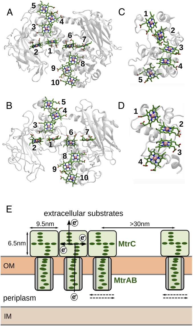
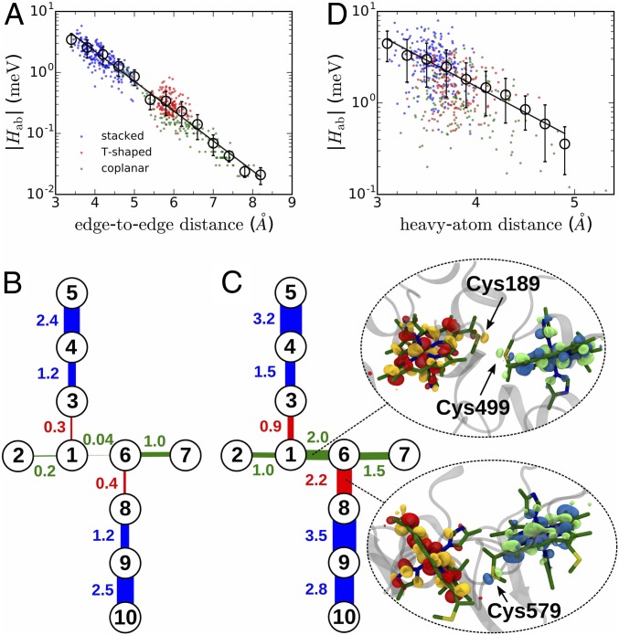
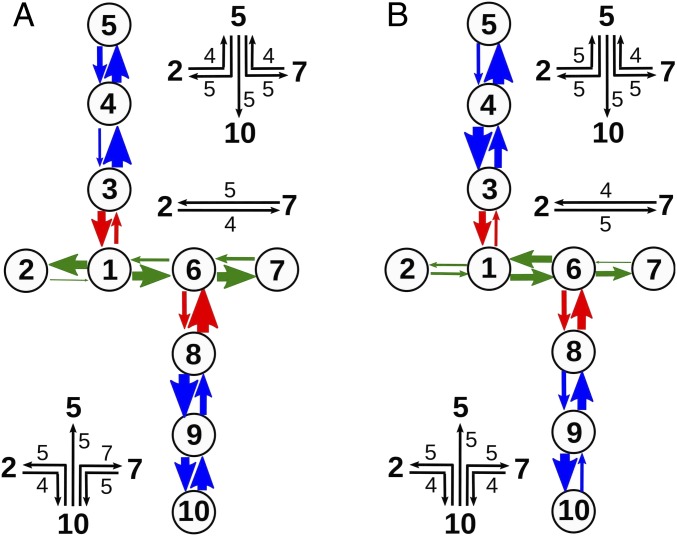
The bacterium Shewanella oneidensis has evolved a sophisticated electron transfer (ET) machinery to export electrons from the cytosol to extracellular space during extracellular respiration. At the heart of this process are decaheme proteins of the Mtr pathway, MtrC and MtrF, located at the external face of the outer bacterial membrane. Crystal structures have revealed that these proteins bind 10 c-type hemes arranged in the peculiar shape of a staggered cross that trifurcates the electron flow, presumably to reduce extracellular substrates while directing electrons to neighboring multiheme cytochromes at either side along the membrane. Especially intriguing is the design of the heme junctions trifurcating the electron flow: they are made of coplanar and T-shaped heme pair motifs with relatively large and seemingly unfavorable tunneling distances. Here, we use electronic structure calculations and molecular simulations to show that the side chains of the heme rings, in particular the cysteine linkages inserting in the space between coplanar and T-shaped heme pairs, strongly enhance electronic coupling in these two motifs. This results in an [Formula: see text]-fold speedup of ET steps at heme junctions that would otherwise be rate limiting. The predicted maximum electron flux through the solvated proteins is remarkably similar for all possible flow directions, suggesting that MtrC and MtrF shuttle electrons with similar efficiency and reversibly in directions parallel and orthogonal to the outer membrane. No major differences in the ET properties of MtrC and MtrF are found, implying that the different expression levels of the two proteins during extracellular respiration are not related to redox function.
Keywords: density functional theory; electron transfer; extracellular respiration; heme; molecular dynamics.
Conflict of interest statement
The authors declare no conflict of interest.
Figures
Similar articles
-
Structure of a bacterial cell surface decaheme electron conduit.Proc Natl Acad Sci U S A. 2011 Jun 7;108(23):9384-9. doi: 10.1073/pnas.1017200108. Epub 2011 May 23. Proc Natl Acad Sci U S A. 2011. PMID: 21606337 Free PMC article.
-
Electron flow in multiheme bacterial cytochromes is a balancing act between heme electronic interaction and redox potentials.Proc Natl Acad Sci U S A. 2014 Jan 14;111(2):611-6. doi: 10.1073/pnas.1316156111. Epub 2014 Jan 2. Proc Natl Acad Sci U S A. 2014. PMID: 24385579 Free PMC article.
-
Distinct Electron Conductance Regimes in Bacterial Decaheme Cytochromes.Angew Chem Int Ed Engl. 2018 Jun 4;57(23):6805-6809. doi: 10.1002/anie.201800294. Epub 2018 May 2. Angew Chem Int Ed Engl. 2018. PMID: 29663609
-
Mind the gap: diversity and reactivity relationships among multihaem cytochromes of the MtrA/DmsE family.Biochem Soc Trans. 2012 Dec 1;40(6):1268-73. doi: 10.1042/BST20120106. Biochem Soc Trans. 2012. PMID: 23176466 Free PMC article. Review.
-
Exploring the biochemistry at the extracellular redox frontier of bacterial mineral Fe(III) respiration.Biochem Soc Trans. 2012 Jun 1;40(3):493-500. doi: 10.1042/BST20120018. Biochem Soc Trans. 2012. PMID: 22616858 Review.
Cited by
-
Molecular mechanisms of electron transfer employed by native proteins and biological-inorganic hybrid systems.Comput Struct Biotechnol J. 2020 Dec 14;19:206-213. doi: 10.1016/j.csbj.2020.12.004. eCollection 2021. Comput Struct Biotechnol J. 2020. PMID: 33425252 Free PMC article. Review.
-
Engineering of bespoke photosensitiser-microbe interfaces for enhanced semi-artificial photosynthesis.Chem Sci. 2024 May 21;15(26):9893-9914. doi: 10.1039/d4sc00864b. eCollection 2024 Jul 3. Chem Sci. 2024. PMID: 38966358 Free PMC article. Review.
-
Cofactor Dynamics Couples the Protein Surface to the Heme in Cytochrome c, Facilitating Electron Transfer.J Phys Chem B. 2022 May 19;126(19):3522-3529. doi: 10.1021/acs.jpcb.2c01632. Epub 2022 May 4. J Phys Chem B. 2022. PMID: 35507916 Free PMC article.
-
Kinetic model for reversible radical transfer in ribonucleotide reductase.Proc Natl Acad Sci U S A. 2022 Jun 21;119(25):e2202022119. doi: 10.1073/pnas.2202022119. Epub 2022 Jun 17. Proc Natl Acad Sci U S A. 2022. PMID: 35714287 Free PMC article.
-
Ultrafast Electronic Coupling Estimators: Neural Networks versus Physics-Based Approaches.J Chem Theory Comput. 2023 Jul 11;19(13):4232-4242. doi: 10.1021/acs.jctc.3c00184. Epub 2023 Jun 22. J Chem Theory Comput. 2023. PMID: 37345885 Free PMC article.
References
-
- Myers CR, Nealson KH. Bacterial manganese reduction and growth with manganese oxide as the sole electron acceptor. Science. 1988;240:1319–1321. - PubMed
-
- Zhuang K, Ma E, Lovley DR, Mahadevan R. The design of long-term effective uranium bioremediation strategy using a community metabolic model. Biotechnol Bioeng. 2012;109:2475–2483. - PubMed
-
- Yi H, et al. Selection of a variant of geobacter sulfurreducens with enhanced capacity for current production in microbial fuel cells. Biosens Bioelect. 2009;24:3498–3503. - PubMed
-
- Fitzgerald LA, et al. Aggrandizing power output from shewanella oneidensis mr-1 microbial fuel cells using calcium chloride. Biosens Bioelect. 2012;31:492–498. - PubMed
Publication types
MeSH terms
Substances
LinkOut - more resources
Full Text Sources
