. 2019 Jan 30;13(1):014106.
doi: 10.1063/1.5070068. eCollection 2019 Jan.

3D printed selectable dilution mixer pumps

Affiliations

3D printed selectable dilution mixer pumps

Hua Gong et al. Biomicrofluidics. .

Abstract

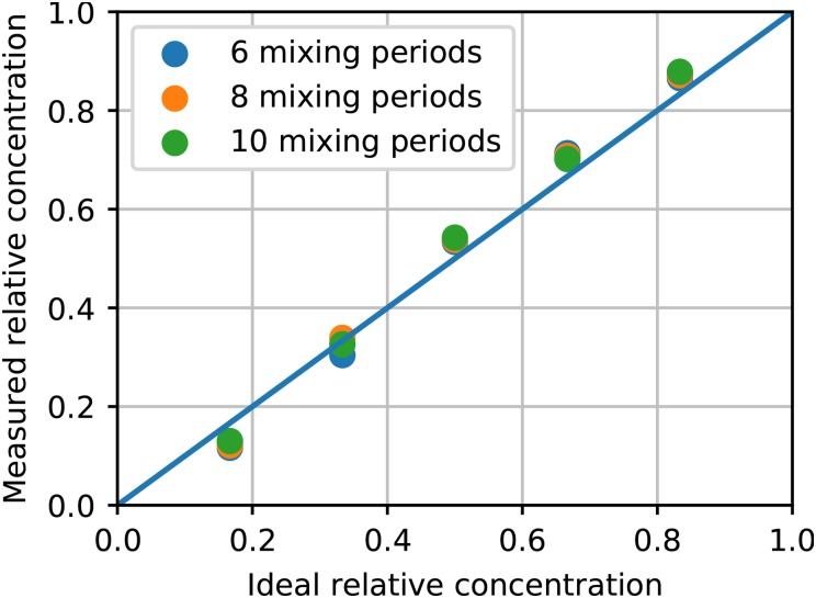
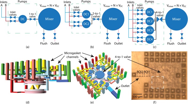
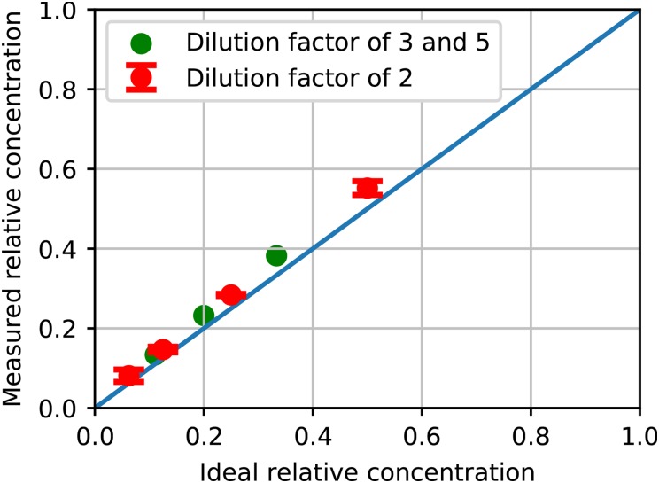
In this paper, we demonstrate the ability to 3D print tightly integrated structures with active valves, pumps, and mixers, and we use our compact chip-to-chip interconnects [Gong et al., Lab Chip 18, 639-647 (2018)] to move bulky world-to-chip connections to separate interface chips for both post-print flushing and post-cure device operation. As example devices, we first examine 3D printed pumps, followed by two types of selectable ratio mixer pumps, a linear dilution mixer pump (LDMP) and a parallelized dilution mixer pump (PDMP), which occupy volumes of only 1.5 mm 3 and 2.6 mm 3 , respectively. The LDMP generates a selectable dilution ratio from a linear set of possibilities, while the PDMP generates a denser set of possible dilutions with a maximum dilution ratio of 1/16. The PDMP also incorporates a new 4-to-1 valve to simultaneously control 4 inlet channels. To characterize LDMP and PDMP operation and performance, we present a new, low-cost video method to directly measure the relative concentration of an absorptive dye on a pixel-by-pixel basis for each video frame. Using this method, we find that 6 periods of the active mixer that forms the core of the LDMP and PDMP are sufficient to fully mix the fluid, and that the generated concentrations track the designed dilution ratios as expected. The LDMP mixes 20 nl per 4.6 s mixer pump period, while the PDMP uses parallelized input pumps to process the same fluid volume with greater choice of dilution ratios in a 3.6 s period.


Figures

FIG. 1.
FIG. 1.
Microfluidic 3D printing fabrication process flow.
FIG. 2.
FIG. 2.
(a) (top) Functional illustration of a 3D printed pump and (bottom) a 3D printed valve in open and closed states. See text for details. (b) CAD drawing of a pump with a serpentine outlet channel. (c) Measured pumping volume for DCs with different diameters and 50μm height for both the fluid and control chambers. The unit of the x-axis dimension, pixel, is the DLP image plane pixel pitch, 7.6μm. (d)–(g) Microscope photos of a pump at various stages in its operation. The DC has the same diameter as the valves, which is 40 pixels. (d)(e): Outlet valve opens, and the meniscus moves back by the volume of the valve upward membrane displacement, Vvalve; (e)(f): DC is actuated, and the meniscus moves forward by the volume of the DC downward membrane displacement, VDC; (f)(g): outlet valve is actuated, and the meniscus moves further forward by the volume of the valve downward membrane displacement, which is the same as its upward membrane displacement, Vvalve.
FIG. 3.
FIG. 3.
(a) Schematic of LDMP. It contains 2 pumps which are connected to a fluid reservoir. They can selectively pump fluid to the mixer which performs mixing. (b) 3D layout of (a). Pumps are stacked on top of the mixer, and the mixer has 2 large DCs connected to each other via cone-shaped channels. (c) Photograph of a 3D printed device designed for characterization of 4 LDMPs on a single chip. (d) Microscope photo of an LDMP which uses microgaskets developed in Ref. . (e) LDMP flushing chip. (f) LDMP operation chip. (g) LDMP device chip assembled with flushing chip. (h) LDMP device chip assembled with operation chip.
FIG. 4.
FIG. 4.
(a) Water and Red flow induced only by gravity. The fluid in the ROI denoted by the dashed box is segregated, as expected. (b) Standard deviation, σ, of relative concentration, Crel(x,y), in the ROI as a function of frames in recorded video.
FIG. 5.
FIG. 5.
The mean and standard deviation of relative concentration Crel(x,y) in the ROI as a function of the frame number. The state (open/closed) of the outlet valve is plotted as the red curve where a pulse corresponds to open. The outlet is initially filled with Water. Near Frame 26 000 (108s) the outlet channel is flushed with Red. (a) Nmix=1. (b) Nmix=2. (c) Nmix=6. (d) Nmix=8. See text for mixing details.
FIG. 6.
FIG. 6.
Measured relative concentration as a function of ideal relative concentration for 6, 8, and 10 mixing periods. The measured relative concentration is averaged over frames in 3 full consecutive mixer pump cycles starting from frame 20 000.
FIG. 7.
FIG. 7.
(a) CAD design of a 3D printed 4-to-1 valve that contains 4 inlet channels and 1 outlet channel. (b) Microscope photo of a fabricated 4-to-1 valve under pressure. The membrane is deflected such that it is in contact with the central area of the bottom of the valve, covering all 4 inlet channels and therefore closing the valve.
FIG. 8.
FIG. 8.
(a)–(c) Schematic of PDMPs with 1, 2, and 4 DIPs, respectively. A DIP has 2 inlet valves to enable pumping from either fluid source. The 1-to-1 valve is a normal valve, but a n-to-1 valve controls connecting n inlets to 1 outlet. (d) and (e) Different perspectives of a PDMP CAD design with 4 pumps and a 4-to-1 valve. The green vertical channels are fluidic channels, and the rest are control (pneumatic) channels. The outlet channel consists of two sections with heights of 50μm (ROI1) and 100μm (ROI2), respectively. (f) Microscope photo of a 3D printed device based on (d) and (e). Inside the white dashed box are 2 inlet valves and a DC.
FIG. 9.
FIG. 9.
Measured relative concentration as a function of ideal relative concentration for different dilution factors using PDMPs. See text for details.

References

    1. Ho C. M. B., Ng S. H., Li K. H. H., and Yoon Y.-J., “3d printed microfluidics for biological applications,” Lab Chip 15, 3627–3637 (2015). 10.1039/C5LC00685F - DOI - PubMed
    1. Au A. K., Huynh W., Horowitz L. F., and Folch A., “3d-printed microfluidics,” Angew. Chem. Int. Ed. 55, 3862–3881 (2016). 10.1002/anie.201504382 - DOI - PMC - PubMed
    1. Waheed S., Cabot J. M., Macdonald N. P., Lewis T., Guijt R. M., Paull B., and Breadmore M. C., “3d printed microfluidic devices: Enablers and barriers,” Lab Chip 16, 1993–2013 (2016). 10.1039/C6LC00284F - DOI - PubMed
    1. Beauchamp M. J., Nordin G. P., and Woolley A. T., “Moving from millifluidic to truly microfluidic sub-100-μm cross-section 3d printed devices,” Anal. Bioanal. Chem. 409, 4311–4319 (2017). 10.1007/s00216-017-0398-3 - DOI - PMC - PubMed
    1. Gong H., Bickham B. P., Woolley A. T., and Nordin G. P., “Custom 3d printer and resin for 18μm×20μm microfluidic flow channels,” Lab Chip 17, 2899–2909 (2017). 10.1039/C7LC00644F - DOI - PMC - PubMed

LinkOut - more resources