

Influence of Intra-Oral Scanner (I.O.S.) on The Marginal Accuracy of CAD/CAM Single Crowns
- PMID: 30769768
- PMCID: PMC6406818
- DOI: 10.3390/ijerph16040544
Influence of Intra-Oral Scanner (I.O.S.) on The Marginal Accuracy of CAD/CAM Single Crowns
Abstract
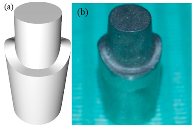
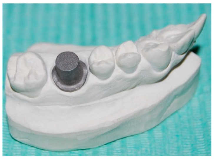
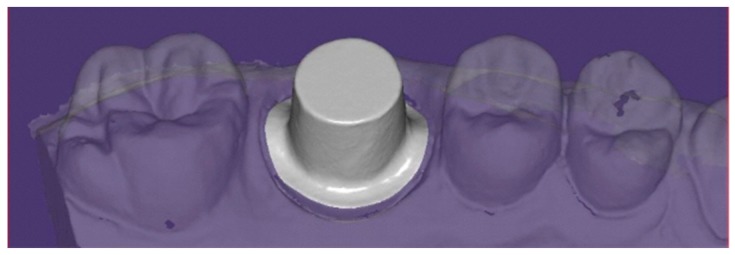
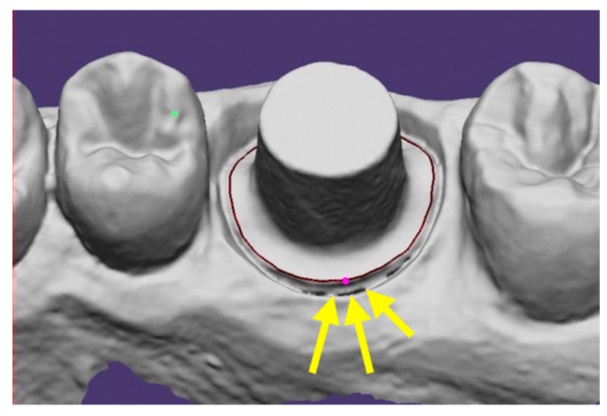
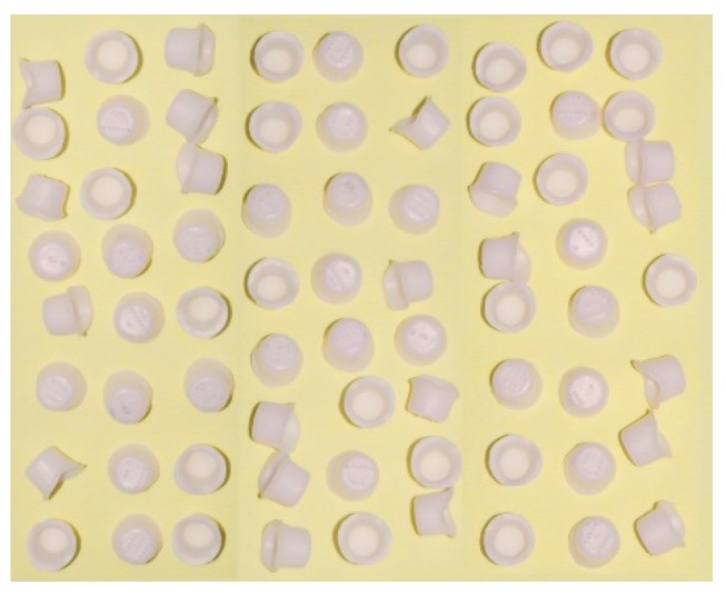
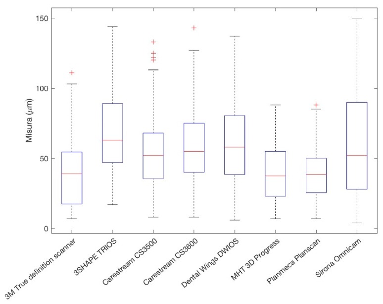
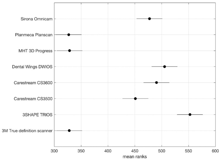
The aim of this in vitro study was to compare the quality of digital workflows generated by different scanners (Intra-oral digital scanners (I.O.S.s)) focusing on marginal fit analysis. A customized chrome-cobalt (Cr-Co) implant abutment simulating a maxillary right first molar was fixed in hemi-maxillary stone model and scanned by eight different I.O.S.s: Omnicam® (Denstply Sirona, Verona, Italy) CS3500®, CS3600®, (Carestream Dental, Atlanta, GA, USA), True Definition Scanner® (3M, St. Paul, MN, USA), DWIO® (Dental Wings, Montreal, Quebec, Canada), PlanScan® (Planmeca Oy, Helsinki, Finland), 3D PROGRESS Plus® (MHT, Verona, Italy), TRIOS 3® (3Shape, Copenhagen, Denmark). Nine scans were performed by each tested I.O.S. and 72 copings were designed using a dental computer-assisted-design/computer-assisted-manufacturing (CAD/CAM) software (exocad GmbH, Darmstadt, Germany). According to CAD data, zirconium dioxide (ZrO₂) copings were digitally milled (Roland DWX-50, Irvine, CA, USA). Scanning electron microscope (SEM) direct vision allowed for marginal gap measurements in eight points for each specimen. Descriptive analysis was performed using mean, standard deviation, and median, while the Kruskal⁻Wallis test was performed to determine whether the marginal discrepancies were significantly different between each group (significance level p < 0.05). The overall mean marginal gap value and standard deviation were 53.45 ± 30.52 μm. The minimum mean value (40.04 ± 18.90 μm) was recorded by PlanScan®, then 3D PROGRESS Plus® (40.20 ± 21.91 μm), True Definition Scanner® (40.82 ± 26.19 μm), CS3500® (54.82 ± 28.86 μm) CS3600® (59,67 ± 28.72 μm), Omnicam® (61.57 ± 38.59 μm), DWIO® (62.49 ± 31.54 μm), while the maximum mean value (67.95 ± 30.41 μm) was recorded by TRIOS 3®. The Kruskal⁻Wallis tests revealed a statistically significant difference (p-value < 0.5) in the mean marginal gaps between copings produced by 3D PROGRESS Plus®, PlanScan, True Definition Scanner, and the other evaluated I.O.S.s. The use of an I.O.S. for digital impressions may be a viable alternative to analog techniques. Although in this in vitro study PlanScan®, 3D PROGRESS Plus® and True Definition Scanner® may have showed the best performances, all I.O.S.s tested could provide clinically encouraging results especially in terms of marginal accuracy, since mean marginal gap values were all within the clinically acceptable threshold of 120 μm.
Keywords: CAD/CAM; SEM; digital impression; marginal accuracy; scanner.
Conflict of interest statement
The authors declare no conflict of interest.
Figures
References
-
- Mormann W.H., Brandestini M., Lutz F. The Cerec system: Computer-assisted preparation of direct ceramic inlays in 1 setting. Quintessenz. 1987;38:457–470. - PubMed
Publication types
MeSH terms
LinkOut - more resources
Full Text Sources
Miscellaneous
