

doi: 10.1016/j.jcmg.2018.12.012.
Epub 2019 Feb 13.
First Clinical Experience With 3-Dimensional Echocardiographic Transillumination Rendering
Affiliations
- PMID: 30772235
- PMCID: PMC7538076
- DOI: 10.1016/j.jcmg.2018.12.012
Item in Clipboard
First Clinical Experience With 3-Dimensional Echocardiographic Transillumination Rendering
JACC Cardiovasc Imaging.
2019 Sep.
No abstract available
Keywords: 3D echocardiography; conventional rendering; transillumination.
Figures
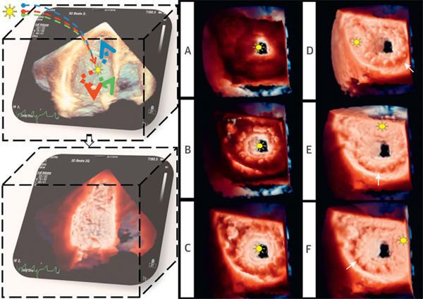
(Left) TI post-processing. The light, modeled with multiple wavelengths, is positioned in the data set. Tissue absorption creates shadows, highlights structures, and enhances depth perception. (Right) Effect of changes in the light position. (A to C) The light was moved along the z plane (depth) from the left ventricular to the left atrial cavity. (D to F) The light was moved along the x and y planes within the LA. Different light positions determine different bioprosthesis shadows (white arrows) (Video 1). LA = left atrium; TI = transillumination.
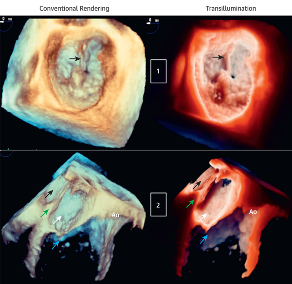
(Case 1) Mitral valve P2 flail due to ruptured chordae (arrows) viewed from the LA (aortic valve 12 o’clock position). The light is in the LA near the ruptured chord to enhance the structural abnormality (Videos 2 and 3). (Case 2) Cor triatriatum. From top to bottom, LA, divided into upper chambers (black arrows) and lower chambers (white arrows) by the membrane (green arrows), mitral valve (blue arrows), and Ao. The light is at the lower left atrial cavity, close to the congenital membrane to improve cavity depth perception (Videos 4 and 5). Ao = aortic valve; other abbreviations as in Figure 1.
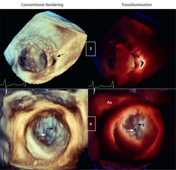
(Case 3) Bi-leaflet mechanical mitral valve prosthesis with paravalvular leakage (arrows) viewed from the LA. The light is in the LV behind the paravalvular leakage, outlining the orifice edges (Videos 6 and 7). (Case 4) Mitral valve P3 scallop perforation (black arrows) and small, central mal-coaptation (white arrows) are shown. The light is on the valvular plane at the level of the P3 perforation orifice, helping to outline both orifices that otherwise cannot be visualized with conventional rendering (Videos 8 and 9). LV = left ventricle.
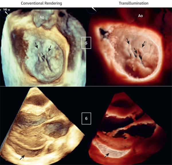
(Case 5) Mitral valve P2 and P3 flail scallops due to multiple ruptured chords (arrows) viewed from the LA. The light is in the LA, close to the valvular plane, slightly anterior to P2. TI rendering enhances the visualization of the ruptured chords and flail scallops (Videos 10 and 11). (Case 6) Inferolateral pericardial effusion (arrows) viewed from a parasternal long-axis acquisition. The light is located deep inside the inferolateral pericardial sac, resulting in a clear definition of the pericardial effusion and cavity (Videos 12 and 13).
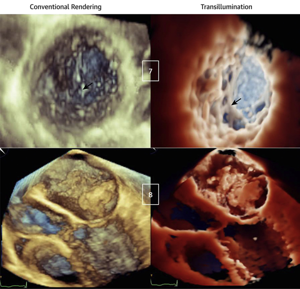
(Case 7) Apical region of left ventricular noncompaction. The light is in the LV, close to the trabecular inferolateral region, resulting in a clear visualization of the extensive trabeculations in comparison with conventional rendering (arrows) (Videos 14 and 15). (Case 8) Left atrial myxoma with diastolic prolapsing across the mitral valve. The light is in the LA, above the tumor. Although the mass is obvious with conventional rendering, it appears poorly defined, whereas TI rendering underlines mass contours, attachments, dynamic motion, and interaction with the mitral valve (Videos 16 and 17). Abbreviations as in Figures 1 and 3.
Publication types
MeSH terms
Grants and funding
LinkOut - more resources
Full Text Sources
Medical
