. 2019 Feb 18;19(4):839.
doi: 10.3390/s19040839.

Real-Time Estimation for Roll Angle of Spinning Projectile Based on Phase-Locked Loop on Signals from Single-Axis Magnetometer

Affiliations

Real-Time Estimation for Roll Angle of Spinning Projectile Based on Phase-Locked Loop on Signals from Single-Axis Magnetometer

Zhaowei Deng et al. Sensors (Basel). .

Abstract

As roll angle measurement is essential for two-dimensional course correction fuze (2-D CCF) technology, a real-time estimation of roll angle of spinning projectile by single-axis magnetometer is studied. Based on the measurement model, a second-order frequency-locked loop (FLL)-assisted third-order phase-locked loop (PLL) is designed to obtain rolling information from magnetic signals, which is less dependent on the amplitude and able to reduce effect from geomagnetic blind area. Method of parameters optimization of tracking loop is discussed in the circumstance of different speed and it is verified by six degrees of freedom (six degrees of freedom (DoF)) trajectory. Also, the measurement error is analyzed to improve the accuracy of designed system. At last, experiments on rotary table are carried out to validate the proposed method indicating the designed system is able to track both phase and speed accurately and stably. The standard deviation (SD) of phase error is no more than 3°.

Keywords: 2-D CCF; FLL-assisted PLL; magnetic sensor; roll angle measurement; spinning projectile.


Conflict of interest statement

The authors declare no conflicts of interest.

Figures
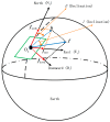
Figure 1
Figure 1
Description of geomagnetic field.
Figure 2
Figure 2
Here are figures to describe projectile body based on a model of 155 mm artillery projectile launched by howitzer: (a) Description of body coordinate system and (b) description of the cross-section.
Figure 3
Figure 3
Description of compensation angle.
Figure 4
Figure 4
Process of obtaining roll angle.
Figure 5
Figure 5
Block diagram of phase-locked loop in frequency domain (Laplace transform).
Figure 6
Figure 6
Block diagram of discrete time system of combined loop filter.
Figure 7
Figure 7
Designed tracking system.
Figure 8
Figure 8
(a) Descriptions of amplitude–frequency characteristic. (b) Descriptions of step response of third-order PLL.
Figure 9
Figure 9
(a) Description of amplitude–frequency characteristic. (b) Description of step response of second-order FLL.
Figure 10
Figure 10
Model of 6-degrees of freedom (DoF) trajectory: (a) Trajectory of projectile and (b) information of the speed, pitch and yaw from 6-DoF.
Figure 11
Figure 11
Amplitude of BZ changing in flight: (a) Description of the amplitude of BZ. (b) Description of part of the amplitude of BZ (within 0.03 second).
Figure 12
Figure 12
Tracking results. (a) Description of BZ and local replicas (amplitude of local replicas is amplified 8 times for the convenience of comparison). (b) Description of phase of local replicas. (c) Description of the output of phase discriminator. (d) Description of error of phase tracking.
Figure 13
Figure 13
Tracking results: (a) Description of the contrast of speed and (b) description of error of speed tracking.
Figure 14
Figure 14
Comparison of compensation angle based on different geomagnetic information in north direction (a), east (b) direction, south (c) direction, and west (d) direction.
Figure 15
Figure 15
Deviation of compensation angle caused by different geomagnetic information in north direction (a), east (b) direction, south (c) direction, and west (d) direction.
Figure 16
Figure 16
SD and mean of deviation of compensation angle caused by the noise.
Figure 17
Figure 17
Compensation angle and deviation when yaw is 0° and 180°: (a,c) Description of compensation angle in the north and south direction and (b,d) description deviation of compensation angle.
Figure 18
Figure 18
Cross-section and geomagnetic vector.
Figure 19
Figure 19
Experiments on rotary table.
Figure 20
Figure 20
Design of integrated circuit.
Figure 21
Figure 21
Results of group 1: (a) Description of digital amplitude of BZ; (b) Comparison of pulses produced by hall sensor and controller and (c) is part of (b); (d) Description of speed figured out from controller; (e) Description of speed error and phase error.
Figure 21
Figure 21
Results of group 1: (a) Description of digital amplitude of BZ; (b) Comparison of pulses produced by hall sensor and controller and (c) is part of (b); (d) Description of speed figured out from controller; (e) Description of speed error and phase error.
Figure 22
Figure 22
Results of group 2: (a) Description of digital amplitude of BZ; (b) Comparison of pulses produced by hall sensor and controller; (d) Description of speed figured out from controller; (e) Description of speed error and phase error.
Figure 23
Figure 23
Results of group 3: (a) Description of digital amplitude of BZ; (b) Comparison of pulses produced by hall sensor and controller; (d) Description of speed figured out from controller; (e) Description of speed error and phase error.

References

    1. Carlucci D., Pellen R., Pritchard J., Demassi W. Defense Technical Information Center; Fort Belvoir, VA, USA: 2010. Smart Projectiles: Design Guidelines and Development Process Keys to Success.
    1. Mahajan C., Motghare V. Smart Munitions. Defence Sci J. 2010;3:159–163. doi: 10.14429/dsj.60.334. - DOI
    1. Yuan W., Zhang J.Q., Yang F. Study on Stable Scanning of Terminal Sensitivity Projectile and Hardware-in-the-Loop Simulation System. Pure Appl. Math. J. 2015;4:24–27. doi: 10.11648/j.pamj.s.2015040501.15. - DOI
    1. Daso D.A. Weapons of Choice: The Development of Precision Guided Munitions (Review) Technol. Culture. 2007;49:252–254. doi: 10.1353/tech.2008.0021. - DOI
    1. Wang Z.F., Wang H. Target Location of Loitering Munitions Based on Image Matching; Proceedings of the 2011 6th IEEE Conference on Industrial Electronics and Applications; Beijing, China. 21–23 June 2011; pp. 606–609. - DOI