. 2019 Feb 28;10(1):978.
doi: 10.1038/s41467-019-08969-6.

Monolithic lithium niobate photonic circuits for Kerr frequency comb generation and modulation

Affiliations

Monolithic lithium niobate photonic circuits for Kerr frequency comb generation and modulation

Cheng Wang et al. Nat Commun. .

Abstract

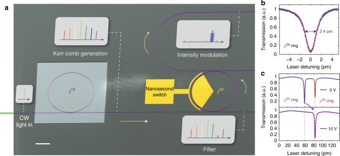
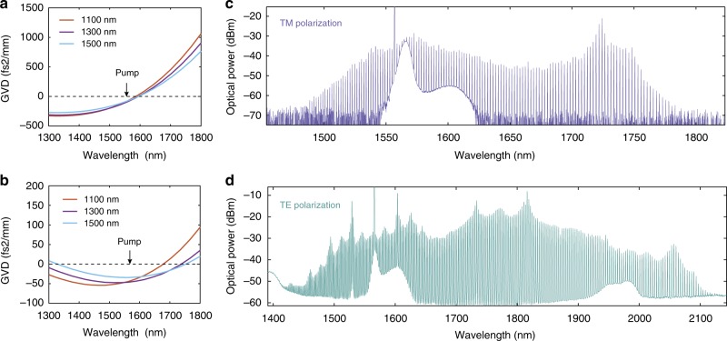
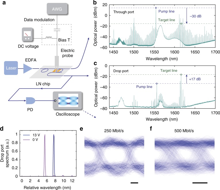
Microresonator Kerr frequency combs could provide miniaturised solutions for a wide range of applications. Many of these applications however require further manipulation of the generated frequency comb signal using photonic elements with strong second-order nonlinearity (χ(2)). To date these functionalities have largely been implemented as discrete components due to material limitations, which comes at the expense of extra system complexity and increased optical losses. Here we demonstrate the generation, filtering and electro-optic modulation of a frequency comb on a single monolithic integrated chip, using a nanophotonic lithium-niobate platform that simultaneously possesses large electro-optic (χ(2)) and Kerr (χ(3)) nonlinearities, and low optical losses. We generate broadband Kerr frequency combs using a dispersion-engineered high-Q lithium-niobate microresonator, select a single comb line using an electrically programmable add-drop filter, and modulate the intensity of the selected line. Our results pave the way towards monolithic integrated frequency comb solutions for spectroscopy, data communication, ranging and quantum photonics.


Conflict of interest statement

C.W., M.Z. and M.L. are involved in developing lithium-niobate technologies at HyperLight Corporation. The other authors declare no competing interests.

Figures

Fig. 1
Fig. 1
Monolithic integrated photonic circuit for frequency comb generation and manipulation. a A false-colour scanning electron microscope (SEM) image showing a fabricated lithium-niobate nanophotonic circuit that consists of a microresonator frequency comb generator (χ(3)) and an electro-optically tuneable add-drop filter (χ(2)). The comb generation area is air cladded to achieve anomalous dispersion, whereas the rest of the chip is cladded in SiO2. Continuous-wave (CW) pump light first passes through the dispersion-engineered microring resonator to generate a frequency comb. The generated frequency comb is then filtered by an add-drop microring filter. At the drop port of the filter, a single target comb line is selected by applying an external bias voltage on the integrated electrodes to align the filter passband with the comb line. Finally, the selected comb line can be modulated at high speeds via the χ(2) effect. Scale bar: 50 µm. b Optical transmission spectrum of the χ(3) microring resonator. The measured loaded (intrinsic) quality (Q) factor of transverse-electric (TE) polarised mode is 6.6×10⁵ (1.1×10⁶). c Transmission spectra at the through port when different direct-current (DC) bias voltages are applied. At zero bias (top plot), the comb resonance (red dip) has a 24-pm mismatch with the filter resonance (blue dip). Applying a bias of 10 V can align the two resonances (bottom plot), showing a measured electrical tuning efficiency of 2.4 pm V−1.
Fig. 2
Fig. 2
Broadband frequency comb generation. a, b Numerically simulated group-velocity dispersions (GVD) at telecom wavelengths for LN waveguides with different top widths. Anomalous dispersions (GVD < 0) can be achieved for both transverse-magnetic (TM) (a) and transverse-electric (TE) (b) modes. c, d Generated frequency comb spectra when the input laser is tuned into resonance with either TM (c) or TE (d) modes at a pump power of ~300 mW in the bus waveguide. The generated combs have a line spacing of ~ 250 GHz, and span ~300 nm (c) and ~700 nm (d) for TM and TE modes, respectively
Fig. 3
Fig. 3
On-chip filtering and modulation of a frequency comb. a Simplified characterisation setup. b, c Measured optical spectra at the through (b) and the drop (c) ports of the filter, picking out a target comb line at ~1616 nm. The filter shows 47 dB suppression of the pump light. d Zoom-in view of the drop-port output spectra near the target line at different DC bias voltages. Applying a bias voltage of 13 V shifts the target from one comb line to the next one. e, f Applying AC electric signals could modulate the intensity of the selected comb line at 250 Mbit s−1 (e) and 500 Mbit s−1 (f). Eye diagrams are measured by sending a random-binary voltage sequence to the filter, and monitoring the real-time output optical power. Open-eye operations can be achieved for both bit rates. Scale bars: 1 ns. AWG arbitrary waveform generator, EDFA erbium-doped fibre amplifier, PD photodetector

References

    1. Udem T, Holzwarth R, Hänsch TW. Optical frequency metrology. Nature. 2002;416:233–237. doi: 10.1038/416233a. - DOI - PubMed
    1. Ye, J. & Cundiff, S. T. Femtosecond Optical Frequency Comb: Principle, Operation and Applications. (Springer Science & Business Media, New York, NY, 2005).
    1. Kippenberg TJ, Holzwarth R, Diddams SA. Microresonator-based optical frequency combs. Science. 2011;332:555–559. doi: 10.1126/science.1193968. - DOI - PubMed
    1. Papp SB, et al. Microresonator frequency comb optical clock. Optica. 2014;1:10–14. doi: 10.1364/OPTICA.1.000010. - DOI
    1. Ferdous F, et al. Spectral line-by-line pulse shaping of on-chip microresonator frequency combs. Nat. Photonics. 2011;5:770–776. doi: 10.1038/nphoton.2011.255. - DOI

Publication types