Review
. 2018 Mar 23:7:17168.
doi: 10.1038/lsa.2017.168. eCollection 2018.

Liquid crystal display and organic light-emitting diode display: present status and future perspectives

Affiliations
Review

Liquid crystal display and organic light-emitting diode display: present status and future perspectives

Hai-Wei Chen et al. Light Sci Appl. .

Abstract

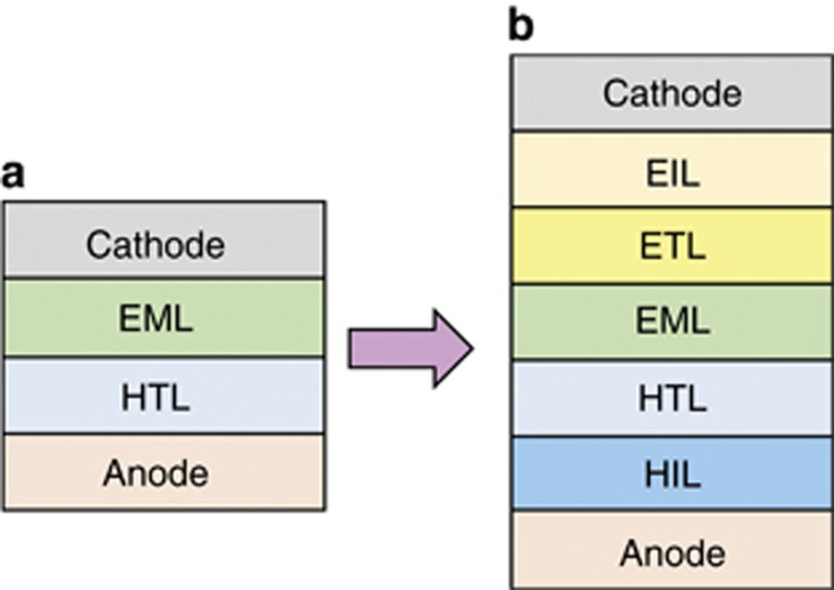
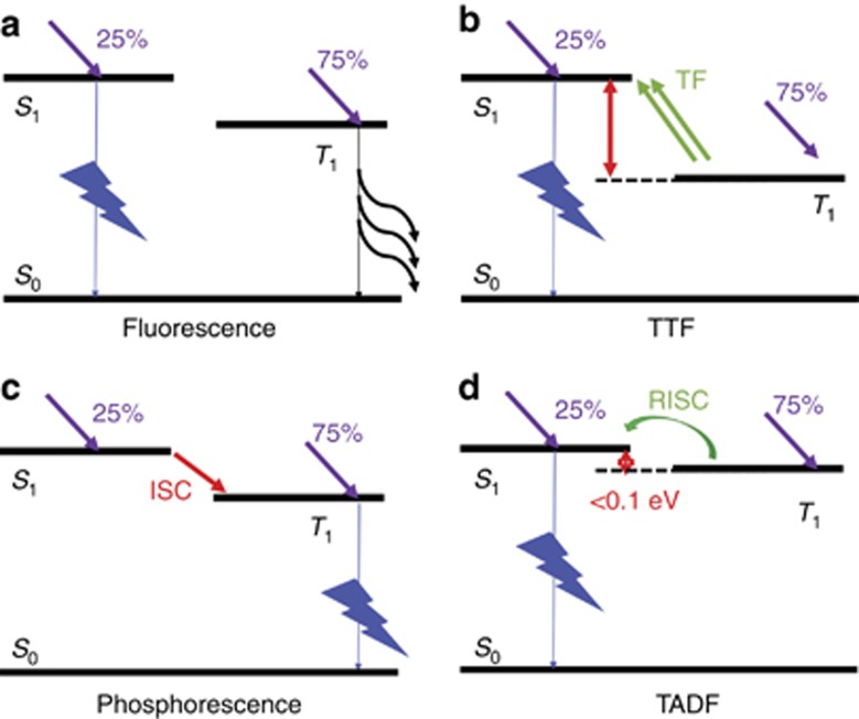
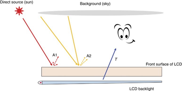
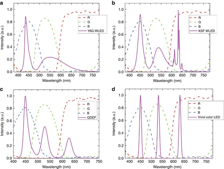
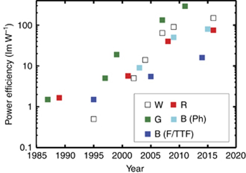
Recently, 'Liquid crystal display (LCD) vs. organic light-emitting diode (OLED) display: who wins?' has become a topic of heated debate. In this review, we perform a systematic and comparative study of these two flat panel display technologies. First, we review recent advances in LCDs and OLEDs, including material development, device configuration and system integration. Next we analyze and compare their performances by six key display metrics: response time, contrast ratio, color gamut, lifetime, power efficiency, and panel flexibility. In this section, we focus on two key parameters: motion picture response time (MPRT) and ambient contrast ratio (ACR), which dramatically affect image quality in practical application scenarios. MPRT determines the image blur of a moving picture, and ACR governs the perceived image contrast under ambient lighting conditions. It is intriguing that LCD can achieve comparable or even slightly better MPRT and ACR than OLED, although its response time and contrast ratio are generally perceived to be much inferior to those of OLED. Finally, three future trends are highlighted, including high dynamic range, virtual reality/augmented reality and smart displays with versatile functions.

Keywords: ambient contrast ratio; liquid crystal displays; motion picture response time; organic light-emitting diode.


Conflict of interest statement

The authors declare no conflict of interest.

Figures

Figure 1
Figure 1
Schematic diagram of an LCD. BEF, brightness enhancement film; BLU, backlight unit; DBEF, dual brightness enhancement film; LGP, light guide plate.
Figure 2
Figure 2
Schematic diagram of the (a) TN mode, (b) VA mode, (c) IPS mode and (d) FFS mode. The LC director orientations are shown in the voltage-off (left) and voltage-on (right) states.
Figure 3
Figure 3
Schematic diagram of an OLED. (a) Basic structure proposed by Tang and VanSlyke in 1987. (b) Multi-layer structure employed in current OLED products. EIL, electron-injection layer; ETL, electron-transporting layer; EML, emitting layer; HTL, hole-transporting layer; HIL, hole-injection layer.
Figure 4
Figure 4
Illustration of the emission mechanisms of OLEDs: (a) fluorescence, (b) TTF, (c) phosphorescence, and (d) TADF. ISC, intersystem crossing; RISC, reverse intersystem crossing; TF, triplet fusion.
Figure 5
Figure 5
Calculated MPRT as a function of the LC (or OLED) response time at different frame rates.
Figure 6
Figure 6
Schematic diagram of two types of reflections for an LCD (or OLED).
Figure 7
Figure 7
Calculated ACR as a function of different ambient light conditions for LCD and OLED TVs. Here we assume that the LCD peak brightness is 1200 nits and OLED peak brightness is 600 nits, with a surface reflectance of 1.2% for both the LCD and OLED. (a) LCD CR: 5000:1, OLED CR: infinity; (b) LCD CR: 20 000:1, OLED CR: infinity.
Figure 8
Figure 8
Calculated ACR as a function of different ambient light conditions for LCD and OLED smartphones. Reflectance is assumed to be 4.4% for both LCD and OLED. (a) LCD CR: 2000:1, OLED CR: infinity; (b) LCD CR: 3000:1, OLED CR: infinity. (LCD peak brightness: 600 nits; OLED peak brightness: 500 nits).
Figure 9
Figure 9
Transmission spectra of color filters and emission spectra of (a) YAG WLED, (b) KSF WLED, (c) QDEF and (d) Vivid Color LED. KSF, potassium silicofluoride; QDEF, quantum dot enhancement film; WLED, white light-emitting diode; YAG, yttrium aluminum garnet.
Figure 10
Figure 10
(a) Luminance decay curves for the blue OLED with different initial luminance values. (b) Estimated T50 under different initial luminance values.
Figure 11
Figure 11
Power efficiency of white, red, green and phosphorescent blue and fluorescent/TTF blue OLEDs over time. Data are compiled from Refs. , , , , , , , , , , , , , , , , , , , , , .

References

    1. Castellano JA. Handbook of Display Technology. Amsterdam, The Netherlands: Elsevier; 2012.
    1. Chigrinov VG. Liquid Crystal Devices: Physics and Applications. Boston, MA, USA: Artech House; 1999.
    1. Schadt M. Milestone in the history of field-effect liquid crystal displays and materials. Jpn J Appl Phys 2009; 48: 03B001.
    1. Yeh P, Gu C. Optics of Liquid Crystal Displays. New York, USA: John Wiley & Sons; 2010.
    1. Yang DK, Wu ST. Fundamentals of Liquid Crystal Devices. 2nd edn. New York, USA: John Wiley & Sons; 2014.