. 2018 Feb 9:7:17138.
doi: 10.1038/lsa.2017.138. eCollection 2018.

Monolithically integrated stretchable photonics

Affiliations

Monolithically integrated stretchable photonics

Lan Li et al. Light Sci Appl. .

Abstract

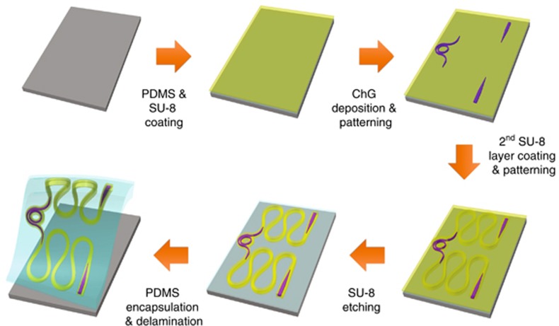
Mechanically stretchable photonics provides a new geometric degree of freedom for photonic system design and foresees applications ranging from artificial skins to soft wearable electronics. Here we describe the design and experimental realization of the first single-mode stretchable photonic devices. These devices, made of chalcogenide glass and epoxy polymer materials, are monolithically integrated on elastomer substrates. To impart mechanical stretching capability to devices built using these intrinsically brittle materials, our design strategy involves local substrate stiffening to minimize shape deformation of critical photonic components, and interconnecting optical waveguides assuming a meandering Euler spiral geometry to mitigate radiative optical loss. Devices fabricated following such design can sustain 41% nominal tensile strain and 3000 stretching cycles without measurable degradation in optical performance. In addition, we present a rigorous analytical model to quantitatively predict stress-optical coupling behavior in waveguide devices of arbitrary geometry without using a single fitting parameter.

Keywords: chalcogenide glass; integrated photonics; optical resonator; strain-optical coupling; stretchable photonics.


Conflict of interest statement

The authors declare no conflict of interest.

Figures

Figure 1
Figure 1
(ad) Top-view micrographs of a stretchable device (a, b) in its undeformed state and (c, d) at 36% nominal tensile strain; the arrow in c indicates the stretching direction; (e) schematic diagram of the experimental characterization setup; (f) a photo of a stretched device under test; (g) measured TE-polarization Q-factors of ChG/SU-8 (labeled as ‘ChG’) and SU-8/PDMS (labeled as ‘SU-8’) resonator devices at 1310 and 1550 nm wavelengths; (h) normalized optical transmittance spectra of a ChG/SU-8 stretchable resonator at different nominal strain levels; (i) Q-factors of ChG/SU-8 resonator devices before and after 3000 stretching cycles at 41% nominal strain. The error bars indicate standard deviations of resonant peaks between the wavelength ranges of 1540–1570 nm. DUT, device under test.
Figure 2
Figure 2
Micro-mechanical FEM simulations: (a) strain distribution in an Euler-spiral-shaped ChG waveguide: the insets plot the strain profiles at high-symmetry points of the Euler spiral structure; (b) strain field in the stretchable device structure shown in Figure 1a; (c) schematic top-view layout of a ChG micro-ring resonator; (d) stress components along the azimuth of a ChG micro-ring resonator in the stretchable device structure of Figure 1a. The strain components are defined with respect to the coordinate systems illustrated in c and z is the out-of-plane direction. All the simulation results correspond to the case of 41% nominal tensile strain. Max., maximum.
Figure 3
Figure 3
Schematic fabrication process flow of the stretchable photonic devices.
Figure 4
Figure 4
(a) Schematic layout of the calibration sample; (b) cross-sectional structure of the calibration sample; (c) schematic illustration of the F-P cavity design, which consists of a straight waveguide segment situated between a pair of Bragg grating reflectors; (d) top-view SEM micrograph of the waveguide Bragg grating reflector; (e) comparison of the experimentally determined strain-induced resonance shifts according to Figure 1h (points) and our theoretical prediction (solid line). Note that the theory does not involve any fitting parameters from the stretchable device measurement; (f, g) calculated relative contributions of photoleastic effects, waveguide cross-sectional modification, and waveguide length change to overall strain-induced resonance shift (normalized as unity) when in-plane uniaxial tensile stress is applied f along the resonator waveguide and g perpendicular to the waveguide. The positive/negative signs indicate red/blue shifts, respectively. Insets illustrate the stressed waveguide configurations.

References

    1. Hu JJ, Li L, Lin HT, Zhang P, Zhou WD et al. Flexible integrated photonics: where materials, mechanics and optics meet [Invited]. Opt Mater Express 2013; 3: 1313–1331.
    1. Li L, Lin HT, Michon J, Huang YZ, Li JY et al. A new twist on glass: a brittle material enabling flexible integrated photonics. Int J Appl Glass Sci 2017; 8: 61–68.
    1. Dangel R, Horst F, Jubin D, Meier N, Weiss J et al. Development of versatile polymer waveguide flex technology for use in optical interconnects. J Lightwave Technol 2013; 31: 3915–3926.
    1. Swatowski BW, Amb CM, Breed SK, Deshazer DJ, Weidner WK et al. Flexible, stable, and easily processable optical silicones for low loss polymer waveguides. Proc SPIE 2013; 8622: 862205.
    1. Li L, Zou Y, Lin HT, Hu JJ, Sun XC et al. A fully-integrated flexible photonic platform for chip-to-chip optical interconnects. J Lightwave Technol 2013; 31: 4080–4086.