. 2019 Jun;67(6):401-417.
doi: 10.1369/0022155419836436. Epub 2019 Mar 8.

Histological Criteria that Distinguish Human and Mouse Bone Formed Within a Mouse Skeletal Repair Defect

Affiliations

Histological Criteria that Distinguish Human and Mouse Bone Formed Within a Mouse Skeletal Repair Defect

Xiaonan Xin et al. J Histochem Cytochem. 2019 Jun.

Abstract

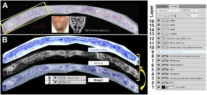
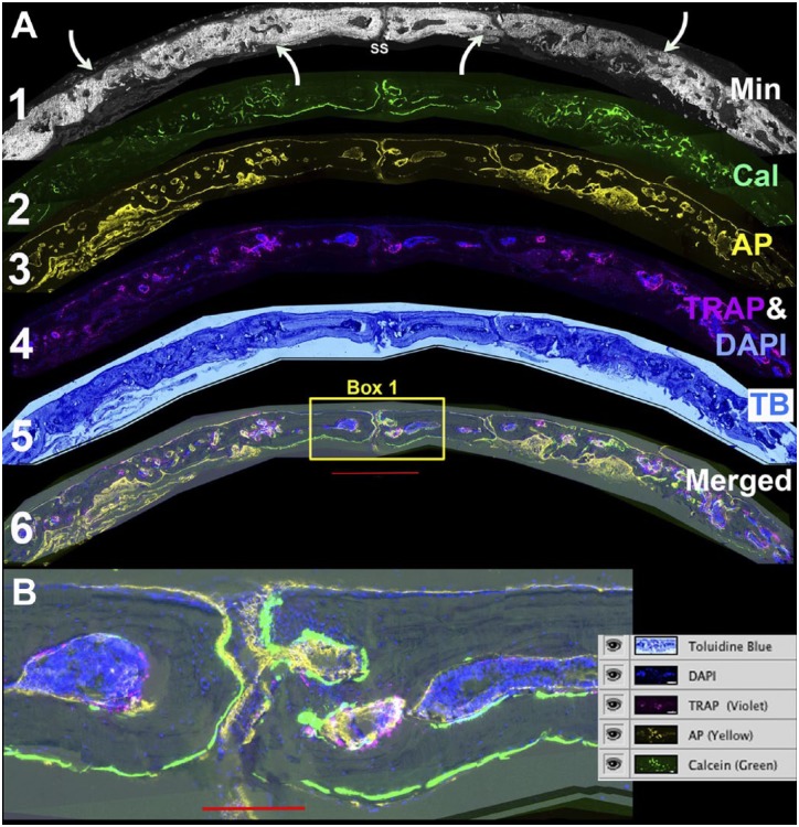
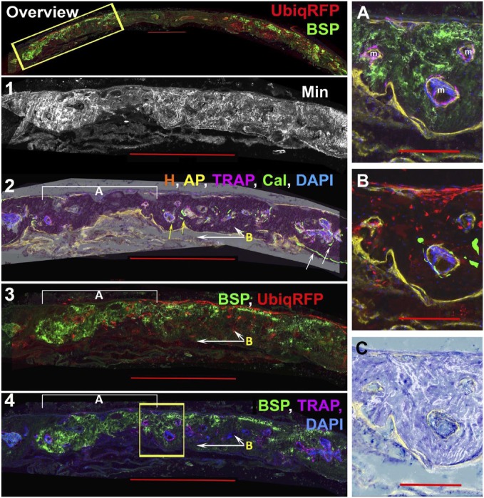
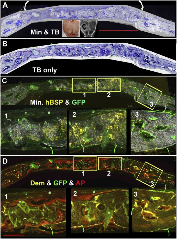
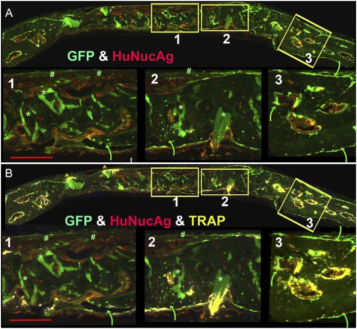
The effectiveness of autologous cell-based skeletal repair continues to be controversial in part because in vitro predictors of in vivo human bone formation by cultured human progenitor cells are not reliable. To assist in the development of in vivo assays of human osteoprogenitor potential, a fluorescence-based histology of nondecalcified mineralized tissue is presented that provides multiple criteria to distinguish human and host osteoblasts, osteocytes, and accumulated bone matrix in a mouse calvarial defect model. These include detection of an ubiquitously expressed red fluorescent protein reporter by the implanted human cells, antibodies specific to human bone sialoprotein and a human nuclear antigen, and expression of a bone/fibroblast restricted green fluorescent protein reporter in the host tissue. Using low passage bone marrow-derived stromal cells, robust human bone matrix formation was obtained. However, a striking feature is the lack of mouse bone marrow investment and osteoclasts within the human bone matrix. This deficiency may account for the accumulation of a disorganized human bone matrix that has not undergone extensive remodeling. These features, which would not be appreciated by traditional decalcified paraffin histology, indicate the human bone matrix is not undergoing active remodeling and thus the full differentiation potential of the implanted human cells within currently used mouse models is not being realized.

Keywords: GFP; RFP; bone cell transplantation; bone matrix; calvarial defect model; cryohistology; epifluorescence imaging; immunostaining; mineralized tissues; primary human MSCs; xenograft.


Conflict of interest statement

Competing Interests: The author(s) declared no potential conflicts of interest with respect to the research, authorship, and/or publication of this article.

Figures

Figure 1.
Figure 1.
Creation and use of the image stack. (A) Root image stack: This file contains all the intensity-adjusted layers, x-rays, photographs, scale bars, and a file title stamp. To the right is a screen shot of the layers window that illustrates all the layers that the file contains. Layers 2 through 11 are superimposed. Layer 2 is the mineral layer and is adjusted to the normal image mode. Layers 3 to 7 are fluorescent signals that are adjusted to the screen mode at 100% opacity. Layers 8 and 9 are chromogenic images that are in the screen mode at 50% opacity. Layer 9 is highlighted and its properties (screen, 50% opacity) are shown in the first line of the layer file. This root file is maintained as a multilayered .pdf file and will provide the primary source for all subsequent figures. (B) Example of flat file used for data presentation. The toluidine blue image (9) and mineral layer (2) are placed in a new file, overlaid, aligned, and merged into a single (flat) .jpg file. The resolution (300 pixels/inch) and image size (~40″ × 19″) enables creation of enlarged subregions (e.g., yellow box in Fig. 1A) that can be presented in the context of the overall lower resolution flat image (Fig. 3, overview layer). Four scale bar lines ranging for 100 to 1000 µm are deposited within the stack for use in subsequent composite figure development. Abbreviations: RAC, ring aperture contrast; BSP, bone sialoprotein; TRAP, tartrate resistant acid phosphatase; DAPI, 4′,6-diamidino-2-phenylindole.
Figure 2.
Figure 2.
Defining the osteogenic landscape of the repair field. (A) Individual layers of the stack are assembled to characterize the major features of the repair process. Layer 1: Accumulated mineral from which the overall orientation of the defect field is related to the sagittal suture (SS) and the boundaries of the repair are identified by the relative intensity of newly formed versus pre-existing mineralized bone (curved arrows). Layer 2: Calcein labeling of actively mineralizing bone surfaces. Both the accumulated mineral and mineral labeling signals are removed in the TRAP step. Layer 3: AP enzymatic activity. This step assesses the osteogenic activity of the repair process and is performed after the TRAP step. Layer 4. TRAP (violet) and DAPI (blue). The two are paired to emphasize the association of the endocortical bone surfaces with the bone marrow islands. The DAPI is also useful to identify cells with the bone matrix. Layer 5: TB. This stain provides a familiar chromogenic context for the fluorescent signals. Layer 6: Merging of all the cellular layers to show their relationship with active bone matrix forming surfaces. (B) Enlarged view of box 1 with a screen shot of the layer file. The green calcein label highlights the active periosteal and endosteal bone surfaces in the region of the SS. Most of the surfaces have an overlying AP (yellow signal). The bone marrow islands are intensely DAPI positive with TRAP-positive foci on the endocortical surface. The scale bar for Fig. 2A = 1000 µm and for Fig. 2B = 200 µm. Abbreviations: TRAP, tartrate resistant acid phosphatase; DAPI, 4′,6-diamidino-2-phenylindole; AP, alkaline phosphatase; TB, toluidine blue.
Figure 3.
Figure 3.
Identification of human bone matrix by the colocalization of ubiq-RFPchry and anti-hBSP. The experiment used a 13-week-old NSG male mouse and the repair tissue was obtained 12 weeks after the surgical procedure. Panel 1 is an overall view of the ubiq-RFPchry (red) and anti-hBSP (green) signals from the same image stack shown in Figs. 1 and 2. These signals emanate primarily from the two repair defect regions. Panels 2 to 4 enlarge the region boxed in the overview panel and also the boxed regions shown in Figs. 1 and 2. Layers 1 and 2 describe the osteogenic landscape based on accumulated mineralized layer 1 and AP (yellow), TRAP (violet), calcein (green), and DAPI (blue) signals (layer 2). The fluorescent signals are layered over the hematoxylin (H) layer, which preserves regions of mineralized bone as a dense red stain. The white arrows point to the strong calcein labeling of the host periosteal and endocortical bone and the relatively rare calcein labeling within the repair region (yellow arrows). As described in layer 3, bracket A is a region that is exclusively human while the white arrows labeled B identify mouse bone that is extending forward from the dural side of host calvarial border. Layer 3 shows the merging of hBSP (green) and ubiq-RFPchry while layer 4 is TRAP (purple) and hBSP (green). Most of the region to the left of the boxed area which co-express hBSP and ubiq-RFPchry lacks TRAP activity, while regions to the right which are hBSP and ubiq-RFPchry negative show marrow islands with TRAP activity. The boxed region are enlarged in Panels (A–C) to better appreciate the interface between the human and mouse-derived bone. Panel A shows the hBSP and TRAP signals while Panel B is ubiq-RFPchry and calcein. This image has a minor stitching error, which misaligns the AP and calcein signals. The AP signal (yellow) is present in both panels. The two panels provide the impression of a gradual ingrowth of mouse cells extending from the dural side into the overlapping human bone. Marrow islands with osteoclasts develop at the interface but not in the interior of the human bone matrix. Panel C superimposes the mineral layer over toluidine blue staining to demonstrate the disordered pattern of mineral deposition as contrasted with the smooth pattern of host bone shown in Fig. 4, Panel C-3. The scale bar for the overview and Panels 1–4 = 1000 µm and for the subpanels A-C is 200 µm. Abbreviations: RFP, red fluorescent protein; hBSP, Human bone sialoprotein; TRAP, tartrate resistant acid phosphatase; DAPI, 4′,6-diamidino-2-phenylindole; AP, alkaline phosphatase.
Figure 4.
Figure 4.
Use of hBSP and host-derived Col3.6GFPtpz to distinguish human and mouse-derived bone matrix. The experiment used a 17-week-old NSG/Col3.6GFPtpz female mouse and the defect was harvested 8 weeks after surgery. (Panel A) Flattened view of the entire root file of a single hole calvarial defect in which the margins of the repair field are indicated by the curved arrows. (Panel B) Toluidine Blue layer. Some of the larger acellular and weak green hydroxyapatite (HA) deposits of the scaffold are indicated by the green asterisk. (C and D) Osteogenic landscape as defined by accumulated mineral, hBSP (yellow), and Col3.6GFPtpz (green) in Panel C and demeclocycline (DEM, yellow) and AP (red) staining in Panel D. Boxes 1, 2, and 3 are enlarged in this and subsequent panels to represent a region primarily composed of human bone (box 1), a region of interface of human and mouse bone (box 2) and adjacent host bone (box 3). Human bone in boxes 1 and 2 is identified by the hBSP signal, the broad layers of AP-positive cells on the bone surface, the unresorbed HA (green asterisk) and the disorganized mineral deposition. The mouse bone lacks the hBSP and HA staining while the forming mouse bone has a narrow layer of AP-positive osteoblasts and matrix shows a uniform pattern of mineral distribution. Strong expression of host-derived Col3.6GFPtpz cells lining the periosteal and endosteal bone are indicated by the curved green arrows in box 3. The reporter also is seen within the bone matrix external to the human bone (box 1) or intermingled with human bone (box 2). Weak expression of the Col3.6GFPtpz reporter is seen in the fibrous tissue overlying the external side of the repair (marked with a green pound sign). The scale bar for the overview panels is 1000 µm and for the subpanels is 200 µm.
Figure 5.
Figure 5.
Use of HuNucAg (red) and host-derived Col3.6GFPtpz (green) to distinguish human and mouse-derived bone matrix. These images including the three boxed regions are derived from the same experiment described in Fig. 4A. Box 1 shows HuNucAg positive cells throughout the matrix and distinct from the Col3.6GFPtpz positive cell indicated by the curved green arrow. However, in box 2, the green arrow points to a region where the two populations of cells are intermingled with the bone matrix, although most of this hBSP positive matrix only shows HuNucAg positive cells. In box 3, all of the matrix is hBSP negative and Col3.6GFPtpz positive cells are distributed on the periosteal and endosteal surfaces. (B) The distribution of TRAP (yellow) is layered over the image shown in Panel A. Box 1 show a punctate distribution within the dural fibrous tissue in the region of unresorbed Hydroxyapatite (HA) and the small ingrowth of mouse bone (green arrow). Box 2 again show larger accumulation of TRAP-positive cells surrounding the HA deposit (yellow caret) and on the bone surface lined with Col3.6GFPtpz positive cells (green arrow). However, in both boxes, no TRAP signal is detected in regions where huNucAg positive cells predominate. In contrast, box 3 shows the expected strong TRAP positivity of cells lining the endocortical bone of the marrow islands. The scale bar for the overview panels is 1000 µm and for the subpanels is 200 µm. Abbreviations: hBSP, Human bone sialoprotein; GFP, green fluorescent protein; AP, alkaline phosphatase; TRAP, tartrate resistant acid phosphatase.

Similar articles

Cited by

References

    1. Bone Therapeutics: A Regenerative Therapy Company. Available from: www.bonetherapeutics.com
    1. Novadip Biosciences. Available from: http://www.novadip.com
    1. Bone Biologics Corp. Available from: http://bonebiologics.com
    1. Derubeis AR, Cancedda R. Bone marrow stromal cells (BMSCs) in bone engineering: limitations and recent advances. Ann Biomed Eng. 2004;32(1):160–65. - PubMed
    1. Panetta NJ, Gupta DM, Longaker MT. Bone regeneration and repair. Curr Stem Cell Res Ther. 2010;5(2):122–28. - PubMed

Publication types

LinkOut - more resources