. 2019 Mar 27;8(3):242-253.e3.
doi: 10.1016/j.cels.2019.02.002. Epub 2019 Mar 6.

Divergent Aging of Isogenic Yeast Cells Revealed through Single-Cell Phenotypic Dynamics

Affiliations

Divergent Aging of Isogenic Yeast Cells Revealed through Single-Cell Phenotypic Dynamics

Meng Jin et al. Cell Syst. .

Abstract

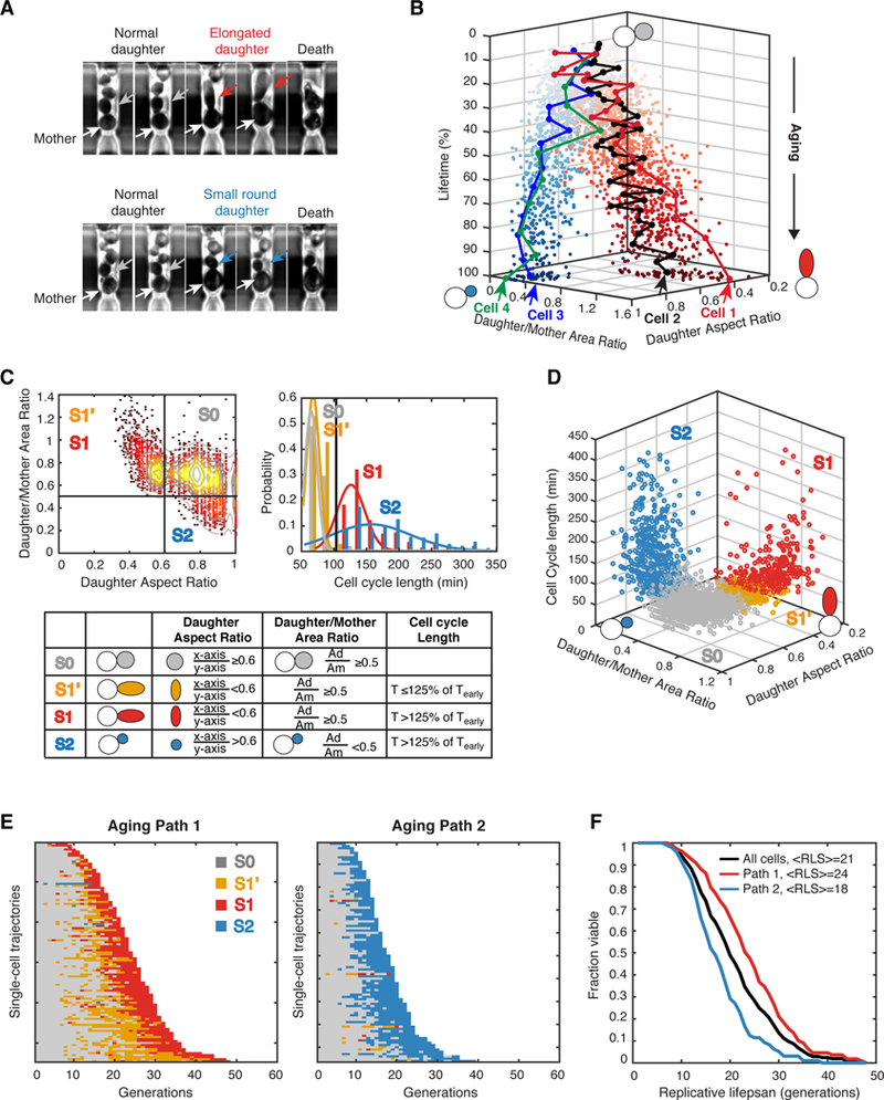
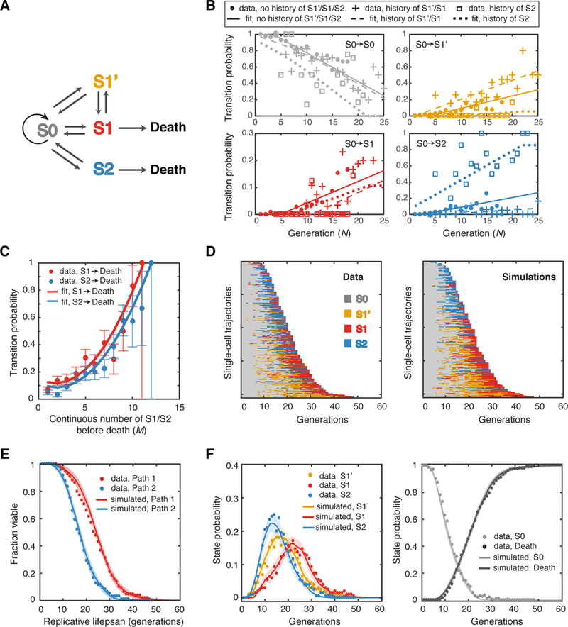
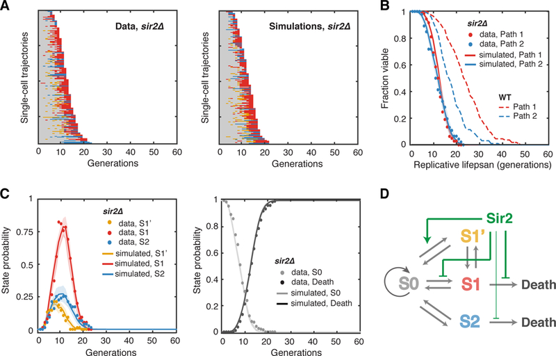
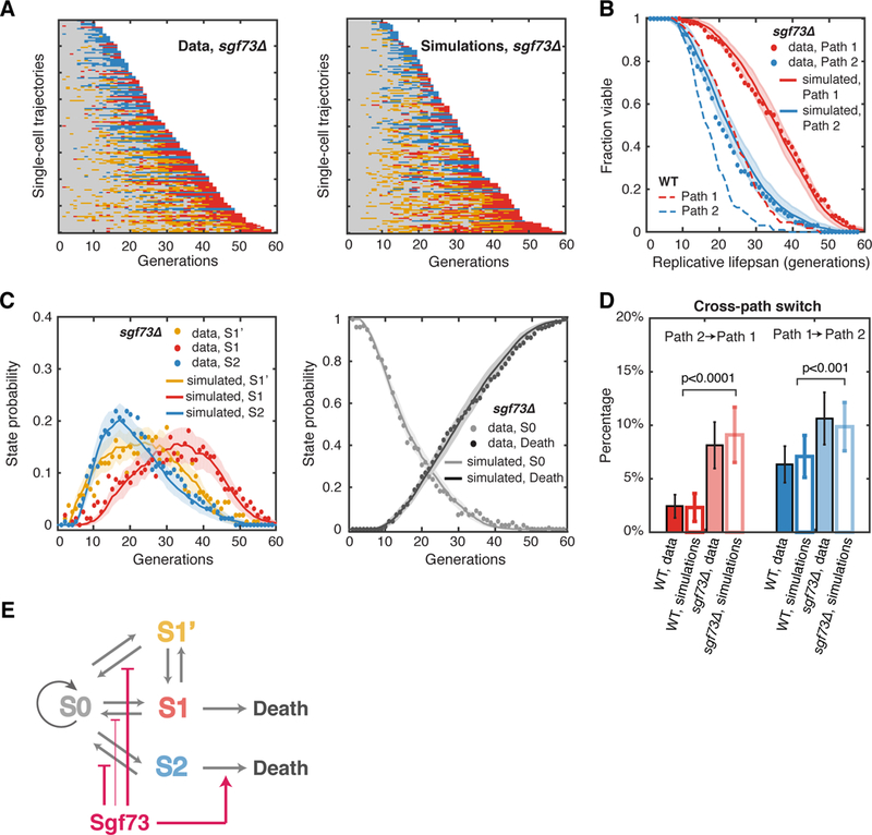
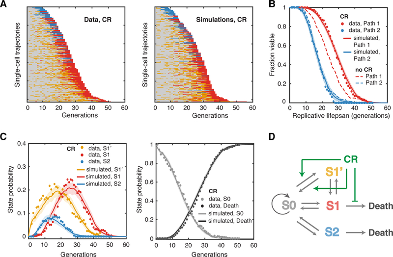
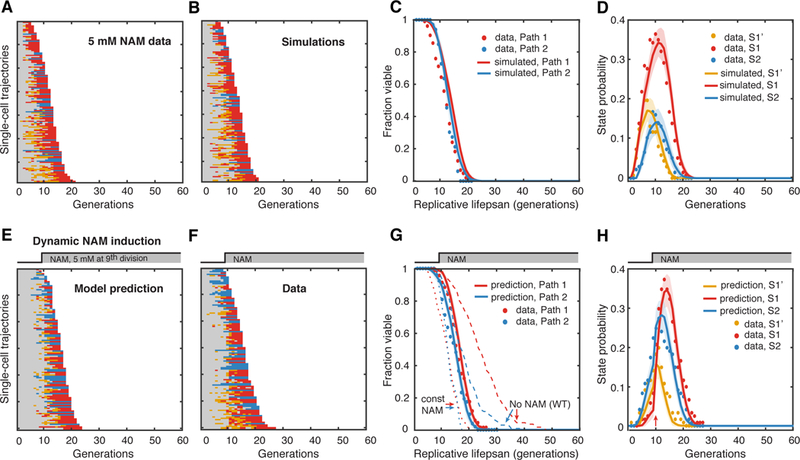
Although genetic mutations that alter organisms' average lifespans have been identified in aging research, our understanding of the dynamic changes during aging remains limited. Here, we integrate single-cell imaging, microfluidics, and computational modeling to investigate phenotypic divergence and cellular heterogeneity during replicative aging of single S. cerevisiae cells. Specifically, we find that isogenic cells diverge early in life toward one of two aging paths, which are characterized by distinct age-associated phenotypes. We captured the dynamics of single cells along the paths with a stochastic discrete-state model, which accurately predicts both the measured heterogeneity and the lifespan of cells on each path within a cell population. Our analysis suggests that genetic and environmental factors influence both a cell's choice of paths and the kinetics of paths themselves. Given that these factors are highly conserved throughout eukaryotes, divergent aging might represent a general scheme in cellular aging of other organisms.

Keywords: caloric restriction; cell fate decision; cellular aging; computational modeling; dynamics; microfluidics; single-cell analysis; sirtuins; stochastic simulations; time-lapse microscopy.


Figures

Figure 1.
Figure 1.. Single-Cell Phenotypic Analysis Reveal Two Divergent Aging Paths.
(A) Representative images of cells illustrating two distinct types of morphological changes during replicative aging. Top row: a mother cell producing elongated daughters during aging; bottom row: a mother cell producing small round daughters during aging. White arrows point to mother cells. Grey arrows point to early normal daughters. Red arrows point to elongated daughters. Blue arrows point to small round daughters. (B) Representative single-cell aging trajectories along two diverged paths toward cell death. Each dot represents the morphology state (Daughter/Mother Area Ratio; Daughter Aspect Ratio) of an aging mother cell at one cell division. Z axis shows the percentage of lifetime. Four representative single-cell trajectories are shown: Cell1 and Cell 2 are moving along the path with elongated daughters (red dots), while Cell 3 and Cell 4 are moving along the path with small round daughters (blue dots). The distance between two adjacent dots in one single-cell trajectory represents the length of this cell division. Arrows indicate the points of cell death. (C) Categorization of age-dependent phenotypic conditions into four states. Daughter/Mother Area Ratio, Daughter Aspect Ratio, and Cell Cycle Length have been measured for each aging mother cell at each cell division. Thresholds used to define states are indicated by black lines. Top left panel: the distribution of daughter aspect ratio vs daughter/mother area ratio. Top right panel: the distributions of cell cycle lengths. Bottom panel: the definitions of the four states (S0, S1’, S1 and S2) based on the three quantified phenotypic metrics. Tearly-the mean cell cycle length of the first 25% of lifespan. See also Figure S8. (D) Distributions of the four states within the 3-D phenotypic metric space. (E) Single-cell state transition trajectories along two distinct aging paths. Each row represents the time trace of a single cell throughout its lifespan. Cells are sorted by their lifespans. Colors represent their cellular states: S0-grey, S1’-orange, S1-red, and S2-blue. Aging Path 1 (left): cells transitioned through S0, S1’ and S1 (n=109); Aging Path 2 (right): cells transitioned through S0 and S2 (n=96). (F) Replicative lifespans of two aging paths. Aging Path 1-red; Aging Path 2-blue; Combined-black.
Figure 2.
Figure 2.. A Stochastic Model for Phenotypic State Transitions During Aging.
(A) Schematic diagram of the discrete-state model. The transitions between states are indicated by arrows. (B) Transition probabilities deduced from data fitting. The fractions of all cells at S0 of a given generation N that switch to S0, S1’, S1 or S2 at the next cell cycle (gray, yellow, red and blue solid circles, respectively) have been computed as a function of age (N). The transition probabilities for S0 cells with the experience of only S0 (no history), the most recent experience of S1’/S1 (history of S1’/S1) or S2 (history of S2) have been calculated separately. The best linear fits are shown by lines with the same color. See also Figures S2, S4 and S9 and Table S1. (C) The transition probabilities from S1 or S2 to death deduced from data fitting. Solid circles represent the fractions of cells that died exactly after M consecutive generations in S1 or S2 over the total number of cells that lived for at least M consecutive generations in S1 or S2 (red-S1, blue-S2). Red and blue curves are best fits of these data using polynomial functions of M. The error bars indicate the expected standard deviation, as described in Method, Computational Modeling. See also Figure S3 and S10. (D) Single-cell state transition trajectories from the data (205 cells) (left), and from stochastic simulations (right). Each row represents the time trace of a single cell throughout its lifespan. (E) The lifespans of two aging paths from simulations (red and blue curves) in comparison with experimental data (red and blue solid circles). Simulated lifespans were averaged from 50 simulations, each with 205 cells. Standard deviations of simulations are shown by shaded areas. (F) Age-dependent state distributions of S1’, S1, S2 (left panel) and S0 and Death (right panel). Solid circles represent the experimental data. Solid curves represent simulated results averaged from 50 simulations with shaded areas showing standard deviations of simulations.
Figure 3.
Figure 3.. Aging-Dependent State Transitions in the Short-Lived sir2Δ Mutant.
(A) Single-cell state transition trajectories of sir2Δ from the data (188 cells, 142 in Path 1, 46 in Path 2) (left), and from stochastic simulations (right). (B) The lifespans of two aging paths in sir2Δ from experimental data (red and blue solid circles) and from simulations (red and blue curves). Dashed curves are the WT lifespans from Figure. 1F for comparison. (C) Age-dependent state distributions of S1’, S1, S2 and S0 and Death in sir2Δ. Solid circles represent the experimental data. Solid curves represent simulated results averaged from 50 simulations with shaded areas indicating standard deviation. (D) Schematic diagram illustrates the effects of Sir2 at specific state transition steps. See also Table S1, Figures S4, S5 and S9.
Figure 4.
Figure 4.. Aging-Dependent State Transitions in the Long-Lived sgf73Δ Mutant.
(A) Single-cell state transition trajectories of sgf73Δ from the data (16O cells, 93 in Path 1, 67 in Path 2) (left), and from stochastic simulations (right). (B) The lifespans of two aging paths in sgf73Δ from experimental data (red and blue solid circles) and from simulations (red and blue curves). Dashed curves are the WT lifespans from Figure. 1F for comparison. (C) Age-dependent state distributions of S1’, S1, S2 and S0 and Death in sgf73Δ. Solid circles represent the experimental data. Solid curves represent simulated results averaged from 50 simulations with the shaded areas showing the standard deviations of simulations. (D) Cross-path switching frequency in WT and sgf73Δ, calculated as a percentage of the total number of cells. Solid bars represent experimental data, with error bars indicating expected standard deviation (details see Method, Computational Modeling). Open bars represent simulations, with error bars indicating standard deviation of 50 simulations. p< 0.001 for both paths with two-sample t-test. See also Table S1, Figures S4, S6, S9 and S10. (E) Schematic diagram illustrates the effects of Sgf73 at specific state transition steps.
Figure 5.
Figure 5.. Aging-Dependent State Transitions under CR.
(A) Single-cell state transition trajectories under CR from the data (257 cells, 192 in Path 1, 65 in Path 2) (left), and from stochastic simulations (right). (B) The lifespans of two aging paths under CR from experimental data (red and blue solid circles) and from simulations (red and blue curves). Dashed curves are the WT lifespans under the glucose-rich conditions from Figure. 1F for comparison. (C) Age-dependent state distributions of S1’, S1, S2 and S0 and Death under CR. Solid circles represent the experimental data. Solid curves represent simulated results averaged from 50 simulations with shaded areas indicating standard deviation. See also Table S1, Figures S4, S7 and S9. (D) Schematic diagram illustrates the effects of CR at specific state transition steps.
Figure 6.
Figure 6.. Model Prediction and Validation for a Dynamic Perturbation of Aging.
(A) Single-cell state transition trajectories under 5 mM constant NAM from the data (137 cells with 104 in Path 1, 33 in Path 2) and (B) from stochastic simulations. (C) The lifespans of two aging paths under 5 mM constant NAM from experimental data (red and blue solid circles) and from simulations (red and blue curves). (D) Age-dependent state distributions of S1’, S1, S2 under 5 mM NAM. Solid circles represent the experimental data. Solid curves represent simulated results averaged from 50 simulations with shaded areas indicating standard deviation. (E) Model-predicted single-cell state transition trajectories of WT cells in response to the step input of 5 mM NAM at 9th generation. (F) Experimental state transition trajectories of WT cells with the step input of 5 mM NAM after 600 mins, when more than 70% of cells just enter their 9th generation. (G) The lifespans of two aging paths in response to the dynamic perturbation. Predictions: red and blue curves; Experimental data: red and blue solid circles. Dashed curves are the lifespans for no NAM treatment and constant NAM treatment. (H) Model-predicted age-dependent state distributions of S1’, S1, S2. Note the sharp increase of S1 and S2 at 10th division (pointed by the red arrow). Solid curves are predictions averaged from 50 simulations with shaded areas indicating standard deviation. Solid circles represent the experimental data. See also Table S1.

References

    1. Auley MT, Mooney KM, Angell PJ, and Wilkinson SJ (2015). Mathematical modelling of metabolic regulation in aging. Metabolites 5, 232–251. - PMC - PubMed
    1. Chen KL, Crane MM, and Kaeberlein M (2016). Microfluidic technologies for yeast replicative lifespan studies. Mech Ageing Dev. - PMC - PubMed
    1. Colman RJ, Anderson RM, Johnson SC, Kastman EK, Kosmatka KJ, Beasley TM, Allison DB, Cruzen C, Simmons HA, Kemnitz JW, et al. (2009). Caloric restriction delays disease onset and mortality in rhesus monkeys. Science 325, 201–204. - PMC - PubMed
    1. Crane MM, and Kaeberlein M (2018). The paths of mortality: how understanding the biology of aging can help explain systems behavior of single cells. Curr Opin Syst Biol 8, 25–31. - PMC - PubMed
    1. Denoth-Lippuner A, Krzyzanowski MK, Stober C, and Barral Y (2014). Role of SAGA in the asymmetric segregation of DNA circles during yeast ageing. Elife 3. - PMC - PubMed

Publication types