. 2019 Feb;475(2222):20180548.
doi: 10.1098/rspa.2018.0548. Epub 2019 Feb 20.

Numerical investigations on bubble-induced jetting and shock wave focusing: application on a needle-free injection

Affiliations

Numerical investigations on bubble-induced jetting and shock wave focusing: application on a needle-free injection

Nikolaos Kyriazis et al. Proc Math Phys Eng Sci. 2019 Feb.

Abstract

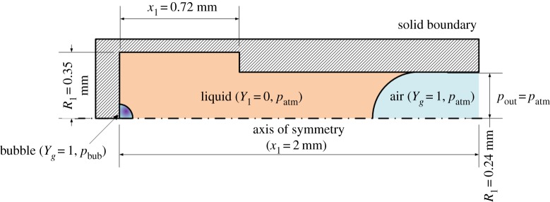
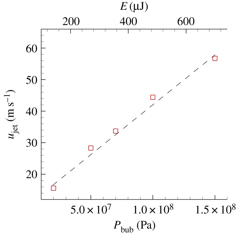
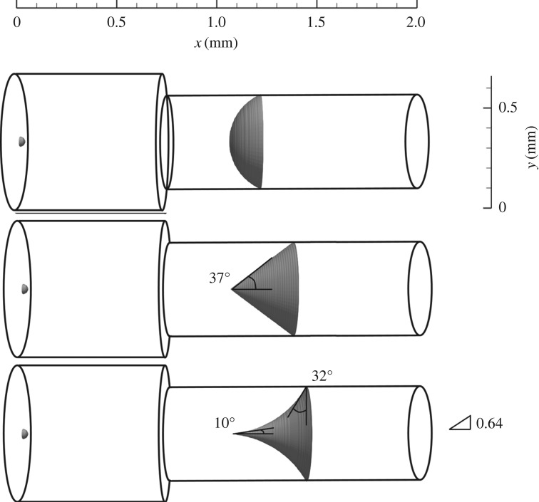
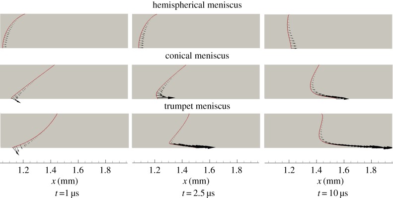
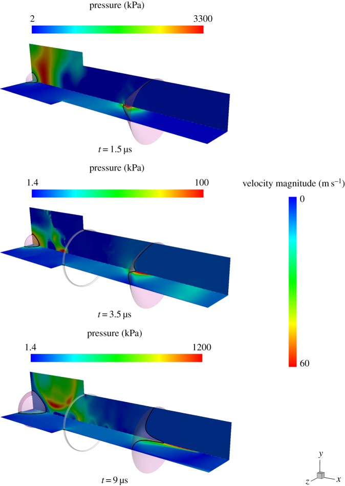
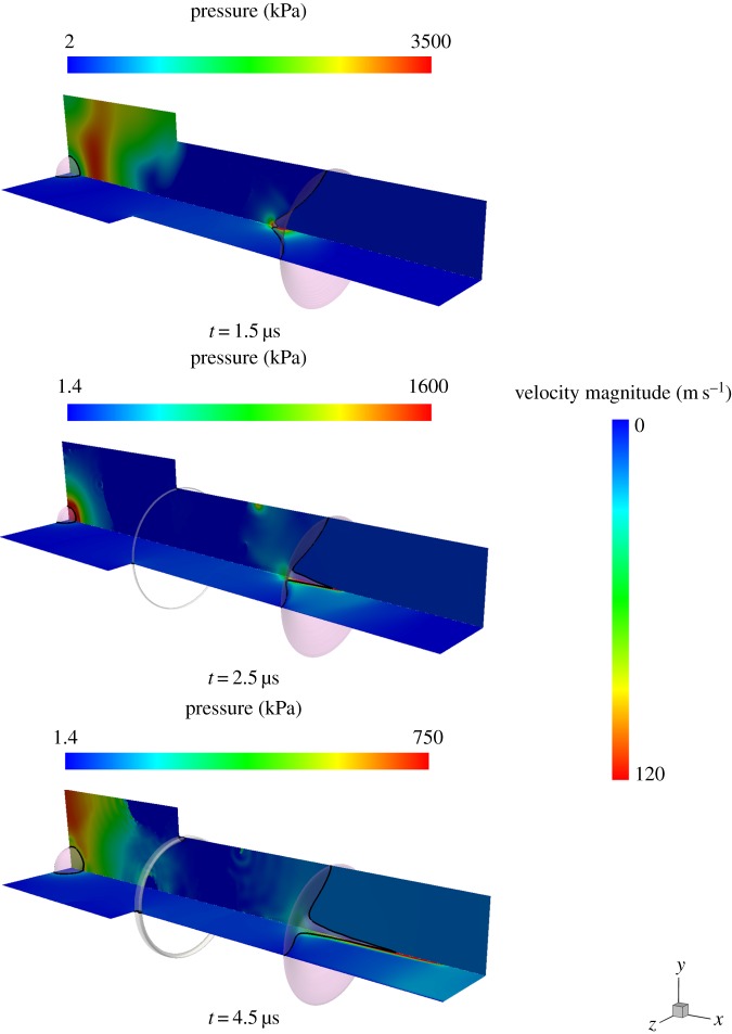
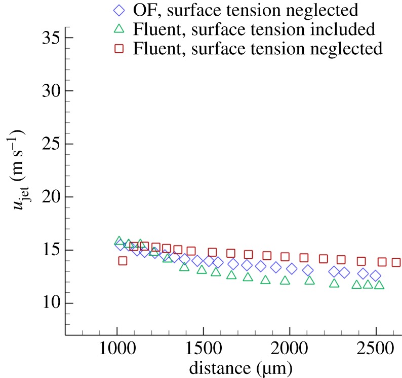
The formation of a liquid jet into air induced by the growth of a laser-generated bubble inside a needle-free device is numerically investigated by employing the compressible Navier-Stokes equations. The three co-existing phases (liquid, vapour and air) are assumed to be in thermal equilibrium. A transport equation for the gas mass fraction is solved in order to simulate the non-condensable gas. The homogeneous equilibrium model is used in order to account for the phase change process between liquid and vapour. Thermodynamic closure for all three phases is achieved by a barotropic Equation of State. Two-dimensional axisymmetric simulations are performed for a needle-free device for which experimental data are available and used for the validation of the developed model. The influence of the initial bubble pressure and the meniscus geometry on the jet velocity is examined by two different sets of studies. Based on the latter, a new meniscus design similar to shaped-charge jets is proposed, which offers a more focused and higher velocity jet compared to the conventional shape of the hemispherical gas-liquid interface. Preliminary calculations show that the developed jet can penetrate the skin and thus, such configurations can contribute towards a new needle-free design.

Keywords: OpenFOAM; cavitating jet; microfluidics; needle-free injection.


Conflict of interest statement

We declare we have no competing interests.

Figures

Figure 1.
Figure 1.
Needleless injection configuration for the hemispherical meniscus geometry: the computational domain (liquid, air, bubble), liquid–gas interface (black line), solid boundary (dashed area) and axis of symmetry (dash dot line). (Online version in colour.)
Figure 2.
Figure 2.
Grid independence study for the needle-free device. Plots of velocity magnitude (a) and gas mass fraction(b) along a line parallel to the x-axis (y = 175 mm) at t = 10 ms. (Online version in colour.)
Figure 3.
Figure 3.
Two-dimensional axisymmetric needle-free device simulation for pbub = 5 × 107 Pa and the standard meniscus shape (case 3). Pressure field on the xy plane and velocity magnitude field on the xz plane are shown, combined with iso-surfaces for vapour volume fraction α = 0.5 (white in the online version, the lighter iso-surface in the printed version) and iso-surface for gas volume fraction Bg = 0.5 (pink in the online version, the darker iso-surface in the printed version). (Online version in colour.)
Figure 4.
Figure 4.
Comparison of case 2 and case 6 with experimental data of Hayasaka et al. [9]. Jet velocity as a function of the distance between the bubble and the air–liquid interface (Bg = 0.5) for laser energy 185 mJ (a) and 650 mJ (b). (Online version in colour.)
Figure 5.
Figure 5.
The influence of the bubble pressure on the jet velocity. (Online version in colour.)
Figure 6.
Figure 6.
Slice on the xy plane for z = 0. Magnitude of the pressure gradient; regimes of vapour volume fraction α≥0.5 are coloured in red in the online version for case 3 (a) and case 7 (b). (Online version in colour.)
Figure 7.
Figure 7.
Initial condition of the meniscus, from top to bottom: hemispherical initialization (case 3), conic initialization (case 8) and trumpet initialization (case 9). The opening angle of the cone in case 8 is 37°. The trumpet aspect ratio in case 9 is 0.64, the contact angle between the interface and the y-axis is 32° and the opening angle of the discretized interface is 10°.
Figure 8.
Figure 8.
Slice on the xy plane for z = 0. Vector field on the interface, for gas volume fraction Bg = 0.5 (red iso-line in the online version, the dark iso-line in the printed version). From top to bottom: hemispherical initialization (case 3), conic initialization (case 8) and trumpet initialization (case 9). The magnitude of the vectors is proportional to the velocity magnitude. (Online version in colour.)
Figure 9.
Figure 9.
Two-dimensional axisymmetric needle-free device simulation for pbub = 5 × 107 Pa and the conical meniscus shape (case 8). Pressure field on the xy plane and velocity magnitude field on the xz plane are shown, combined with iso-surface for vapour volume fraction α = 0.5 (white in the online version, the lighter iso-surface in the printed version) and iso-surface for gas volume fraction Bg = 0.5 (pink in the online version, the darker iso-surface in the printed version). (Online version in colour.)
Figure 10.
Figure 10.
Two-dimensional axisymmetric needle-free device simulation for pbub = 5 × 107 Pa and the trumpet meniscus shape (case 9). Pressure field on the xy plane and velocity magnitude field on the xz plane are shown, combined with iso-surface for vapour volume fraction α = 0.5 (white in the online version, the lighter iso-surface in the printed version) and iso-surface for gas volume fraction Bg = 0.5 (pink in the online version, the darker iso-surface in the printed version). (Online version in colour.)
Figure 11.
Figure 11.
The effect of surface tension is assessed by plotting the jet velocity as a function of the distance between the bubble and the gas–liquid interface for case 2. Comparison between this work in OF, where surface tension was neglected (diamond) and Fluent simulations where surface tension was either considered (triangle) or neglected (red). (Online version in colour.)

Similar articles

Cited by

References

    1. Mitragotri S. 2006. Current status and future prospects of needle-free liquid jet injectors. Nat. Rev. Drug Discovery 5, 543–548. (10.1038/nrd2076) - DOI - PubMed
    1. Berrospe-Rodriguez C, Visser CW, Schlautmann S, Ramos-Garcia R, Rivas DF. 2016. Continuous-wave laser generated jets for needle free applications. Biomicrofluidics 10, 014104 (10.1063/1.4940038) - DOI - PMC - PubMed
    1. Ravi AD, Sadhna D, Nagpaal D, Chawla L. 2015. Needle free injection technology: a complete insight. Int. J. Pharm. Investig. 5, 192–199. (10.4103/2230-973X.167662) - DOI - PMC - PubMed
    1. Kendall M. 2006. Engineering of needle-free physical methods to target epidermal cells for DNA vaccination. Vaccine 24, 4651–4656. (10.1016/j.vaccine.2005.08.066) - DOI - PubMed
    1. Arora A, Prausnitz MR, Mitragotri S. 2008. Micro-scale devices for transdermal drug delivery. Int. J. Pharm. 364, 227–236. (10.1016/j.ijpharm.2008.08.032) - DOI - PMC - PubMed

LinkOut - more resources