Review
. 2019 Mar 14;19(6):1285.
doi: 10.3390/s19061285.

Advanced Micro- and Nano-Gas Sensor Technology: A Review

Affiliations
Review

Advanced Micro- and Nano-Gas Sensor Technology: A Review

Haleh Nazemi et al. Sensors (Basel). .

Abstract

Micro- and nano-sensors lie at the heart of critical innovation in fields ranging from medical to environmental sciences. In recent years, there has been a significant improvement in sensor design along with the advances in micro- and nano-fabrication technology and the use of newly designed materials, leading to the development of high-performance gas sensors. Advanced micro- and nano-fabrication technology enables miniaturization of these sensors into micro-sized gas sensor arrays while maintaining the sensing performance. These capabilities facilitate the development of miniaturized integrated gas sensor arrays that enhance both sensor sensitivity and selectivity towards various analytes. In the past, several micro- and nano-gas sensors have been proposed and investigated where each type of sensor exhibits various advantages and limitations in sensing resolution, operating power, response, and recovery time. This paper presents an overview of the recent progress made in a wide range of gas-sensing technology. The sensing functionalizing materials, the advanced micro-machining fabrication methods, as well as their constraints on the sensor design, are discussed. The sensors' working mechanisms and their structures and configurations are reviewed. Finally, the future development outlook and the potential applications made feasible by each category of the sensors are discussed.

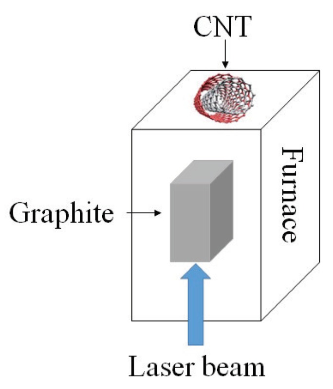
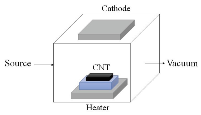
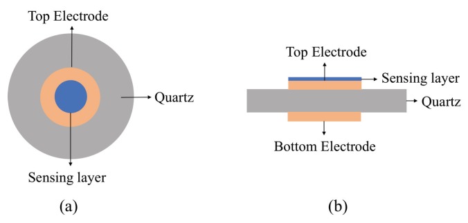
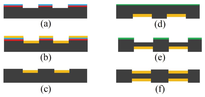
Keywords: acoustic gas sensors; carbon nano-tube (CNT) Sensors; electrochemical gas sensors; fiber-optic gas sensors; metal oxide semiconductor (MOS) sensors; micro-electro mechanical systems (MEMS); organic-based chemiresistive gas sensors; photonic crystal gas sensors; piezoelectric gas sensors; volatile organic compound (VOC).


Conflict of interest statement

The authors declare no conflict of interest.

Figures

Figure 1
Figure 1
Cross sectional view of a MOS sensor comprising of a set of electrodes, micro-heater, and sensing layer fabricated on a thin suspended membrane using MEMS fabrication technology. The change in the sensing material conductance due to the interaction with analytes is proportional to the concentration of the analytes in the sensor environment.
Figure 2
Figure 2
Schematic view of a MOS gas sensor fabrication process (a) thermal oxidation of silicon wafer, (b) photolithography patterning followed by micro-heater deposition, (c) lift-off, (d) deposition of a thin SiO2 layer, (e) photolithography and pattern transfer of micro-electrodes followed by lift-off process, (f) backside etching and deposition of sensing material on the electrodes.
Figure 3
Figure 3
Schematic view of a chemiresistor sensor that measures the sensing material resistance changes between the two interdigited electrodes when exposed to the desired analytes.
Figure 4
Figure 4
Fabricated CNT using an arc discharge method. The chamber with graphite electrodes is filled with helium, hydrogen, or methane. The high temperature causes the graphite to sublimate and move towards the cathode and create a CNT layer on it.
Figure 5
Figure 5
Schematic diagram presenting the pulsed laser ablation method. A graphite target in the reactor evaporates using a laser beam and the CNT layer forms on the surface at the end of the chamber.
Figure 6
Figure 6
Schematic diagram of a PECVD technique where CNT layer is being created on the substrate in a vacuum chamber while a strong electric field generates plasma. The created field causes the nano-tube layers to grow along the electric field and perpendicular to the substrate.
Figure 7
Figure 7
Schematic view of a typical QCM sensor (a) top view and (b) side view. The quartz crystal resonator is sandwiched between two gold electrodes (yellow). The thin film sensing layer on the top of QCM structure (blue) attracts analytes, changing the mass, measuring through sensor resonance frequency shift.
Figure 8
Figure 8
Schematic view of a QCM sensor fabrication steps (a) AT-cut quartz crystal of thickness of approximately 168–330 μm is polished, followed by deposition of chromium layer, photolithography and wet etched steps, (b) Au layer of thickness of approximately 100–200 nm is deposited by electron beam evaporation, (c) gold electrodes are formed by lift-off process, (d) nickel layer is deposited using sputtering technique, (e) nickel layer is patterned and DRIE is carried out to transfer the pattern to the quartz, (f) electrodes are deposited using electron beam evaporation method followed by the lift-off process.
Figure 9
Figure 9
Schematic view of a SAW gas sensor consists of two arrays of reflectors.
Figure 10
Figure 10
Schematic view of a CMUT sensor where the top flexible membrane is coated with a thin layer of PIB.
Figure 11
Figure 11
Schematic view of CMUT fabrication process using fusion bonding methods ((a) wet oxidation of a highly doped silicon substrate followed by a lithography step, (b) growing SiO2 by wet oxidation to further raise the bottom electrode, (c) oxide etch followed by the thermal oxidation of a thin SiO2, deposition of Si3N4, patterning and etching, (d) local oxidation to create anchors, (e) wafer bonding SOI wafer in vacuum followed by annealing, (f) removing carrier wafer and buried oxide layer) as well as sacrificial technique ((g) deposition of Si3N4 insulation layer, (h) deposition of polysilicon bottom electrode, (i) deposition of SiO2 sacrificial layer followed by lithography patterning, (j) deposition of the top membrane polysilicon layer, (k) patterning top membrane to create sacrificial release holes, (l) release of the top membrane using wet etching).
Figure 12
Figure 12
Schematic view of fiber-optic sensors. The probe light enters the optical fiber with initial wavelength λ0 and is introduced on sensing material. The wavelength of light shifts under the influence of change in optical or optoelectronic properties of sensing film by analytes.
Figure 13
Figure 13
Schematic view of a photonic crystal gas sensor. Photonic crystal (PhC) with periodic micro- or nano-patterns are placed between light source and photo detector. Gaseous analytes can pass through the patterns or be condensed in the patterns where they change the effective refractive index, n, or the lattice distance of periodic structure, d. The diffraction wavelength changed by the two factors is detected by the detector based on Bragg’s law.

References

    1. Seiyama T., Kagawa S. Study on a Detector for Gaseous Components Using Semiconductive Thin Films. Anal. Chem. 1966;38:1069–1073. doi: 10.1021/ac60240a031. - DOI
    1. Qu J., Chai Y., Yang S.X. A real-time de-noising algorithm for e-noses in a wireless sensor network. Sensors. 2009;9:895–908. doi: 10.3390/s90200895. - DOI - PMC - PubMed
    1. Refaat T.F., Ismail S., Koch G.J., Rubio M., Mack T.L., Notari A., Collins J.E., Lewis J., De Young R., Choi Y., et al. Backscatter 2-μm Lidar Validation for Atomospheric CO2 Differential Absorption Lidar Applications. IEEE Trans. Geosci. Remote Sens. 2011;49:572–580. doi: 10.1109/TGRS.2010.2055874. - DOI
    1. Donarelli M., Ottaviano L. 2D Materials for Gas Sensing Applications: A Review on Graphene Oxide, MoS2, WS2 and Phosphorene. Sensors. 2018;18:3638. doi: 10.3390/s18113638. - DOI - PMC - PubMed
    1. Wang C., Yin L., Zhang L., Xiang D., Gao R. Metal oxide gas sensors: Sensitivity and influencing factors. Sensors. 2010;10:2088–2106. doi: 10.3390/s100302088. - DOI - PMC - PubMed

MeSH terms

Substances

LinkOut - more resources