

Optical coherence tomography-guided laser marking with tethered capsule endomicroscopy in unsedated patients
- PMID: 30891340
- PMCID: PMC6420285
- DOI: 10.1364/BOE.10.001207
Optical coherence tomography-guided laser marking with tethered capsule endomicroscopy in unsedated patients
Abstract
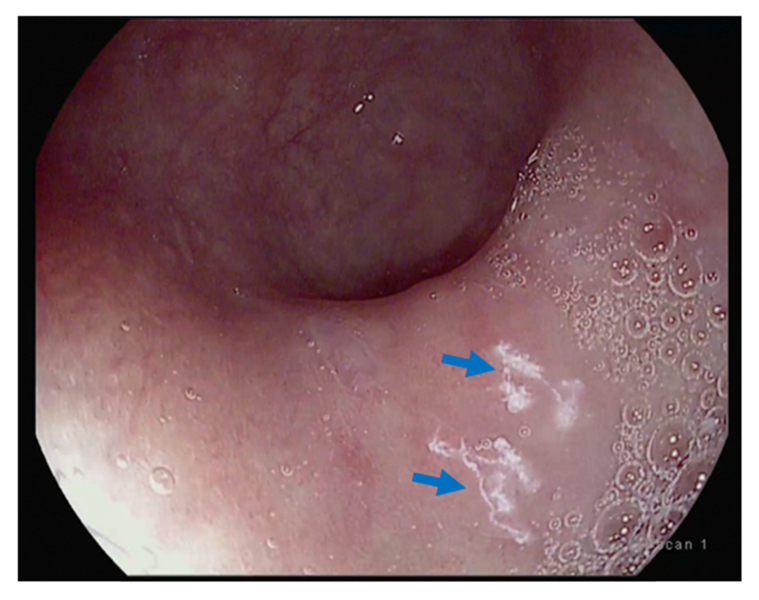
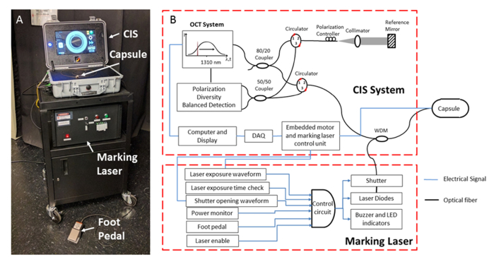
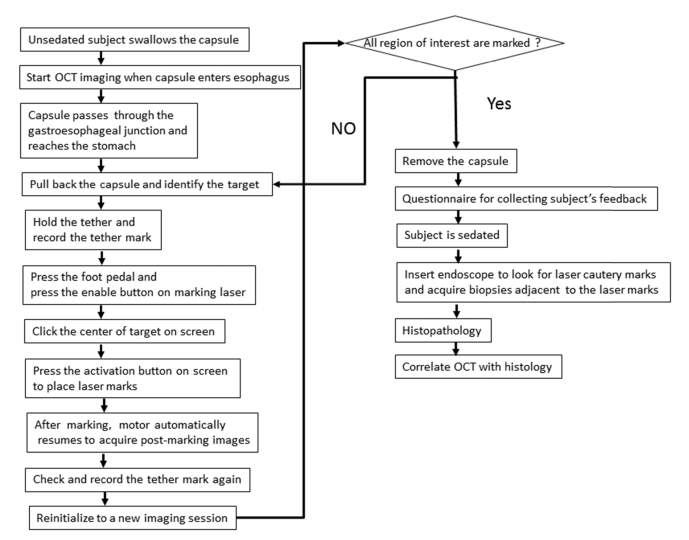
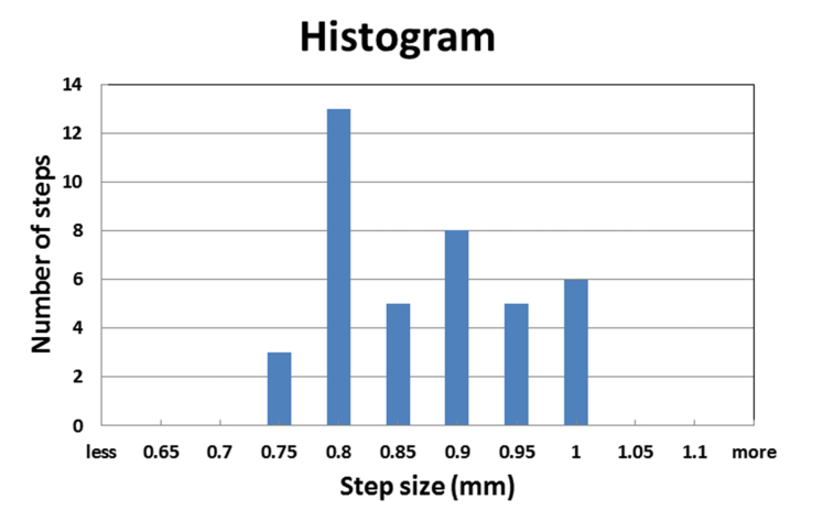
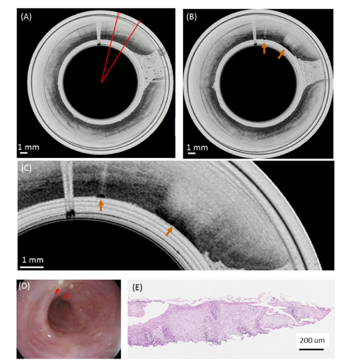
Tethered capsule endomicroscopy (TCE) is an emerging screening technology that comprehensively obtains microstructural OCT images of the gastrointestinal (GI) tract in unsedated patients. To advance clinical adoption of this imaging technique, it will be important to validate TCE images with co-localized histology, the current diagnostic gold standard. One method for co-localizing OCT images with histology is image-targeted laser marking, which has previously been implemented using a driveshaft-based, balloon OCT catheter, deployed during endoscopy. In this paper, we present a TCE device that scans and targets the imaging beam using a low-cost stepper motor that is integrated inside the capsule. In combination with a 4-laser-diode, high power 1430/1450 nm marking laser system (800 mW on the sample and 1s pulse duration), this technology generated clearly visible marks, with a spatial targeting accuracy of better than 0.5 mm. A laser safety study was done on swine esophagus ex vivo, showing that these exposure parameters did not alter the submucosa, with a large, 4-5x safety margin. The technology was demonstrated in living human subjects and shown to be effective for co-localizing OCT TCE images to biopsies obtained during subsequent endoscopy.
Conflict of interest statement
Massachusetts General Hospital has a licensing arrangement with NinePoint Medical. Dr. Tearney has the rights to receive royalties from this licensing arrangement. Dr. Tearney also consults for NinePoint Medical. Dr. Tearney receives sponsored research from Boston Scientific and iLumen Medical.
Figures


Similar articles
-
Feasibility and Safety of Tethered Capsule Endomicroscopy in Patients With Barrett's Esophagus in a Multi-Center Study.Clin Gastroenterol Hepatol. 2022 Apr;20(4):756-765.e3. doi: 10.1016/j.cgh.2021.02.008. Epub 2021 Feb 4. Clin Gastroenterol Hepatol. 2022. PMID: 33549871 Free PMC article.
-
Passively scanned, single-fiber optical coherence tomography probes for gastrointestinal devices.Lasers Surg Med. 2022 Sep;54(7):935-944. doi: 10.1002/lsm.23576. Epub 2022 Jun 16. Lasers Surg Med. 2022. PMID: 35708124 Free PMC article.
-
Dual-modality optical coherence tomography and fluorescence tethered capsule endomicroscopy.Biomed Opt Express. 2021 Jun 21;12(7):4308-4323. doi: 10.1364/BOE.422453. eCollection 2021 Jul 1. Biomed Opt Express. 2021. PMID: 34457416 Free PMC article.
-
Emerging enhanced imaging technologies of the esophagus: spectroscopy, confocal laser endomicroscopy, and optical coherence tomography.J Surg Res. 2015 May 15;195(2):502-14. doi: 10.1016/j.jss.2015.02.045. Epub 2015 Feb 21. J Surg Res. 2015. PMID: 25819772 Review.
-
Advances in Pediatric Diagnostic Endoscopy: A State-of-the-Art Review.JPGN Rep. 2022 Jul 29;3(3):e224. doi: 10.1097/PG9.0000000000000224. eCollection 2022 Aug. JPGN Rep. 2022. PMID: 37168622 Free PMC article. Review.
Cited by
-
High-speed forward-viewing optical coherence tomography probe based on Lissajous sampling and sparse reconstruction.Opt Lett. 2024 Jul 1;49(13):3652-3655. doi: 10.1364/OL.521595. Opt Lett. 2024. PMID: 38950232 Free PMC article.
-
Feasibility and Safety of Tethered Capsule Endomicroscopy in Patients With Barrett's Esophagus in a Multi-Center Study.Clin Gastroenterol Hepatol. 2022 Apr;20(4):756-765.e3. doi: 10.1016/j.cgh.2021.02.008. Epub 2021 Feb 4. Clin Gastroenterol Hepatol. 2022. PMID: 33549871 Free PMC article.
-
Improved sensitivity roll-off in dual reference, buffered spectral-domain optical coherence tomography.J Biomed Opt. 2021 Feb;26(2):025001. doi: 10.1117/1.JBO.26.2.025001. J Biomed Opt. 2021. PMID: 33569937 Free PMC article.
-
Distal planar rotary scanner for endoscopic optical coherence tomography.Biomed Eng Lett. 2024 Feb 19;14(3):583-592. doi: 10.1007/s13534-024-00353-8. eCollection 2024 May. Biomed Eng Lett. 2024. PMID: 38645593 Free PMC article.
-
All-reflective tethered capsule endoscope for multimodal optical coherence tomography in the esophagus.J Biomed Opt. 2024 Sep;29(9):096003. doi: 10.1117/1.JBO.29.9.096003. Epub 2024 Sep 19. J Biomed Opt. 2024. PMID: 39301278 Free PMC article.
References
-
- Gora M. J., Sauk J. S., Carruth R. W., Gallagher K. A., Suter M. J., Nishioka N. S., Kava L. E., Rosenberg M., Bouma B. E., Tearney G. J., “Tethered capsule endomicroscopy enables less invasive imaging of gastrointestinal tract microstructure,” Nat. Med. 19(2), 238–240 (2013).10.1038/nm.3052 - DOI - PMC - PubMed
-
- Liang K., Ahsen O. O., Lee H. C., Wang Z., Potsaid B. M., Figueiredo M., Jayaraman V., Cable A. E., Huang Q., Mashimo H., Fujimoto J. G., “Volumetric Mapping of Barrett’s Esophagus and Dysplasia With en face Optical Coherence Tomography Tethered Capsule,” Am. J. Gastroenterol. 111(11), 1664–1666 (2016).10.1038/ajg.2016.419 - DOI - PMC - PubMed
-
- Gora M. J., Simmons L. H., Quénéhervé L., Grant C. N., Carruth R. W., Lu W., Tiernan A., Dong J., Walker-Corkery B., Soomro A., Rosenberg M., Metlay J. P., Tearney G. J., “Tethered capsule endomicroscopy: from bench to bedside at a primary care practice,” J. Biomed. Opt. 21(10), 104001 (2016).10.1117/1.JBO.21.10.104001 - DOI - PMC - PubMed
-
- Gora M. J., Sauk J. S., Carruth R. W., Lu W., Carlton D. T., Soomro A., Rosenberg M., Nishioka N. S., Tearney G. J., “Imaging the upper gastrointestinal tract in unsedated patients using tethered capsule endomicroscopy,” Gastroenterology 145(4), 723–725 (2013).10.1053/j.gastro.2013.07.053 - DOI - PMC - PubMed
LinkOut - more resources
Full Text Sources