. 2019 Apr 9;116(15):7214-7219.
doi: 10.1073/pnas.1821740116. Epub 2019 Mar 28.

A CRISPR/Cas9-based central processing unit to program complex logic computation in human cells

Affiliations

A CRISPR/Cas9-based central processing unit to program complex logic computation in human cells

Hyojin Kim et al. Proc Natl Acad Sci U S A. .

Abstract

Controlling gene expression with sophisticated logic gates has been and remains one of the central aims of synthetic biology. However, conventional implementations of biocomputers use central processing units (CPUs) assembled from multiple protein-based gene switches, limiting the programming flexibility and complexity that can be achieved within single cells. Here, we introduce a CRISPR/Cas9-based core processor that enables different sets of user-defined guide RNA inputs to program a single transcriptional regulator (dCas9-KRAB) to perform a wide range of bitwise computations, from simple Boolean logic gates to arithmetic operations such as the half adder. Furthermore, we built a dual-core CPU combining two orthogonal core processors in a single cell. In principle, human cells integrating multiple orthogonal CRISPR/Cas9-based core processors could offer enormous computational capacity.

Keywords: biocomputing; genetic engineering; synthetic biology.


Conflict of interest statement

The authors declare no conflict of interest.

Figures
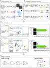
Fig. 1.
Fig. 1.
Design of programmable CRISPR-mediated gene switches. (A) Genetic components of the core processor. As a transcriptional master regulator, dCas9-KRAB was expressed under the constitutive PhCMV promoter. An igRNA-I (IA, orange rectangle; IB, light-blue rectangle) was expressed under the constitutive PhU6 promoter. tRNA (black rhombus) was processed by intrinsic cellular proteins RNase P and RNaseZ to produce gRNA carrying the desired 5′-target sequences without extra nucleotides. Processed igRNA-I was associated with dCas9 protein. (B) Diagram of software architecture layers. Binding sites for igRNA (a or b) and rgRNA (r) with a PAM (black narrow rectangle) sequence between promoter and output were inserted into the output-expressing unit; the output was regulated by the presence of igRNA-I and rgRNA-R. The output can be fluorescent protein, as a final output of the gene circuit, or rgRNA-R as an intermediate regulator of the gene circuit. (C) Diagram of OFF/ON system showing transcriptional regulation by the CRISPR system. In the OFF system, a binding site for igRNA(a) between the PhCMV promoter and the reporter gene ORF was inserted into a reporter gene-expressing unit. The igRNA-IA repressed the transcription of reporter genes. In the ON system, a binding site for igRNA-IA between the PhU6 promoter and rgRNA-R (r1) TSS was inserted into an rgRNA-expressing unit, and a binding site for rgRNA-R1 (r1) between the PhCMV promoter and reporter gene ORF was inserted into a reporter gene-expressing unit. The igRNA activated the reporter gene transcription by repressing rgRNA-R1. Transient transfection of dCas9-KRAB and gRNA expression plasmids repressed reporter gene expression in HEK-293T cells. Cells were transfected with the indicated plasmids for an OFF/ON system (SI Appendix, Table S2) and analyzed by flow cytometry for d2EYFP expression at 48-h posttransfection. The data are displayed as the means ± SD of three independent experiments (n = 3). Mean fluorescence intensities are presented as arbitrary units (a.u.). (D) OFF/ON transcriptional switches were used as building blocks for the digital computing gene circuits, such as Boolean logic gates and the half adder as an arithmetic operator.
Fig. 2.
Fig. 2.
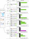
Designing Boolean logic gates (NOR, NIMPLY, and AND) and combinational logic gates (XOR and half adder). Electronic circuit diagram (gate), schematic representation of gene circuit components (software) and the truth table and microscope images and FACS analysis of the performance (output data) of Boolean logic gates and the half adder. All gates have the same core processor but different gene circuit components as software. An A NOR B gate (binding sites for two igRNAs, igRNA-IA and -IB), was placed between the PhCMV promoter and the reporter gene. An A NIMPLY B gate (binding site for igRNA-IB) was placed between the PhU6 promoter and the igRNA rgRNA-R2 and binding sites for igRNA-IA and rgRNA-R2 were placed between the PhCMV promoter and the reporter gene. An A AND B gate (binding sites for igRNA-IA and -IB) was placed between the PhU6 promoter and rgRNA-R1 and -R2 and binding sites for rgRNA-R1 and -R2 were placed between the PhCMV promoter and the reporter gene. An A XOR B gate (binding sites for igRNA-IA and -IB) was placed between the PhU6 promoter and rgRNA-R1 and - R2. Binding sites for igRNA-IA and rgRNA-R2 were placed in the reporter construct, and binding sites for igRNA-IB and rgRNA-R1 were placed in another reporter construct. Half adder: combining A AND B gate and A XOR B gate for a binary function by calculating the carry (mCherry) and sum (d2EYFP). In accordance with the truth table for each gate and the half adder, transfected HEK-293T cells were programmed to produce d2EYFP or mCherry. Gate performance was confirmed using microscopy and flow cytometry. The data are displayed as the means ± SD for three independent experiments (n = 3). Mean fluorescence intensities are presented as a.u.
Fig. 3.
Fig. 3.
Establishing a dual-core CPU with Boolean logic gate applications. Electronic circuit diagram (gate), schematic representation of the gene circuit components (software), and the truth table and FACS analysis of the performance (output data) of Boolean logic gates. All gates have the same two core processors (dSpCas9-KRAB and dSaCas9-KRAB), but different gene circuit components as software. ON switch: the binding site for igRNA-IB (dSpCas9-KRAB) was placed between the PhU6 promoter and rgRNA-R2 and the binding site for rgRNA-R2 (dSaCas9-KRAB) was placed between the PhCMV promoter and the reporter gene. B NIMPLY A gate: the binding site for igRNA-IB (dSpCas9-KRAB) was placed between the PhU6 promoter and rgRNA-R2; and binding sites for igRNA-IA and rgRNA-R2 (dSaCas9-KRAB) were placed between the PhCMV promoter and the reporter gene. The data are displayed as means ± SD for three independent transfections (n = 3). Mean fluorescence intensities are presented as a.u.

References

    1. Xie M, Fussenegger M. Mammalian designer cells: Engineering principles and biomedical applications. Biotechnol J. 2015;10:1005–1018. - PubMed
    1. Bonnet J, Yin P, Ortiz ME, Subsoontorn P, Endy D. Amplifying genetic logic gates. Science. 2013;340:599–603. - PubMed
    1. Gaber R, et al. Designable DNA-binding domains enable construction of logic circuits in mammalian cells. Nat Chem Biol. 2014;10:203–208. - PubMed
    1. Weinberg BH, et al. Large-scale design of robust genetic circuits with multiple inputs and outputs for mammalian cells. Nat Biotechnol. 2017;35:453–462. - PMC - PubMed
    1. Ausländer S, Ausländer D, Müller M, Wieland M, Fussenegger M. Programmable single-cell mammalian biocomputers. Nature. 2012;487:123–127. - PubMed

Publication types

LinkOut - more resources