Review
. 2019 Apr 1;9(4):132.
doi: 10.3390/biom9040132.

Helical Twist and Rotational Forces in the Mitotic Spindle

Affiliations
Review

Helical Twist and Rotational Forces in the Mitotic Spindle

Iva M Tolić et al. Biomolecules. .

Abstract

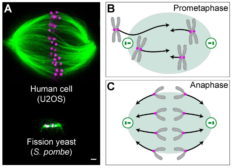
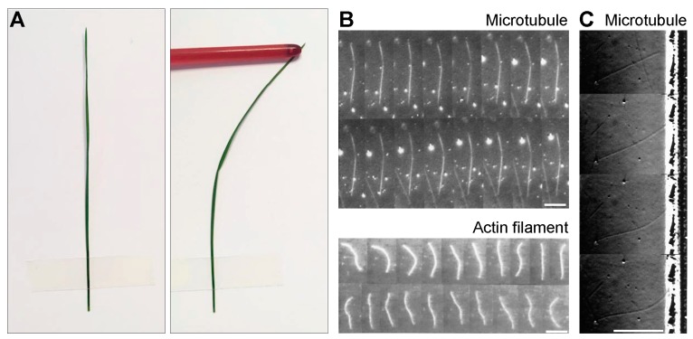
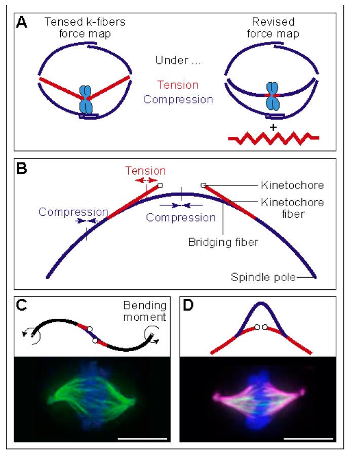
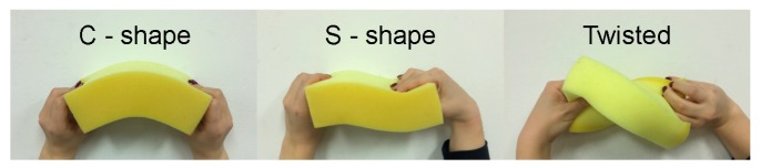
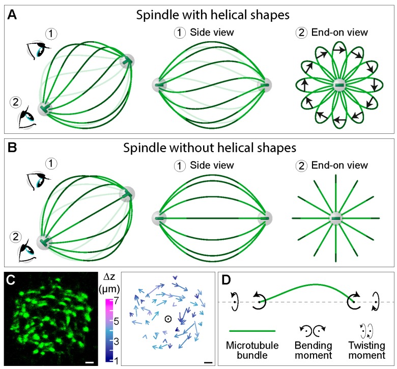
The mitotic spindle segregates chromosomes into two daughter cells during cell division. This process relies on the precise regulation of forces acting on chromosomes as the cell progresses through mitosis. The forces in the spindle are difficult to directly measure using the available experimental techniques. Here, we review the ideas and recent advances of how forces can be determined from the spindle shape. By using these approaches, it has been shown that tension and compression coexist along a single kinetochore fiber, which are balanced by a bridging fiber between sister kinetochore fibers. An extension of this approach to three dimensions revealed that microtubule bundles have rich shapes, and extend not simply like meridians on the Earth's surface but, rather, twisted in a helical manner. Such complex shapes are due to rotational forces, which, in addition to linear forces, act in the spindle and may be generated by motor proteins such as kinesin-5. These findings open new questions for future studies, to understand the mechanisms of rotational forces and reveal their biological roles in cells.

Keywords: forces; microtubules; mitotic spindle; motor proteins; rotational forces; torque.


Conflict of interest statement

The authors declare no conflict of interest.

Figures

Figure 1
Figure 1
Mitotic spindles and forces acting on chromosomes. (A) A mitotic spindle of a human cell (top) and yeast (bottom). Top: a superresolution image obtained by stimulated emission depletion (STED) microscopy (single z-plane) of a metaphase spindle in a live U2OS cell expressing CENP-A-GFP (magenta), with microtubules labeled with SiR-tubulin (green). The image is reproduced with permission from [10]. Bottom: image of a spindle from the fission yeast Schizosaccharomyces pombe, expressing tubulin labeled with GFP (green), and the kinetochore protein Ndc80p labeled with tdTomato (magenta) [11]. Scale bar is 1 µm for both images. Scheme of forces (black arrows) acting on chromosomes (gray) in (B) prometaphase and (C) anaphase. Magenta circles represent kinetochores, green circles are centrosomes with centrioles inside, and the green shaded area marks the spindle region.
Figure 2
Figure 2
From forces to shapes and back. (A) A macroscopic example of a plant stem illustrates the fact that microtubules are intrinsically straight, but can curve under forces. (B) Time-lapse images of a microtubule (top; images are separated by 10 s) and an actin filament (bottom; images are separated by 1.5 s) undergoing thermal fluctuations in curvature. The scale bars represent 10 µm. The curvature fluctuations of the microtubule are small due to its high rigidity. The images are reproduced with permission from [17]. (C) Images of a buckling microtubule encountering a wall (separated by 1 min). Scale bar, 10 µm. The images are reproduced with permission from [18].
Figure 3
Figure 3
Linear and rotational forces that shape the spindle. (A) A classic force map of the spindle, in which kinetochore fibers are under tension and overlap microtubules under compression (left), and a revised force map, where tension and compression coexist along the kinetochore fiber (right). The red element next to the spindle represents a possible non-microtubule component under tension. The image is reproduced with permission from [25]. (B) Force balance based on a theoretical model that includes a bridging fiber as a link between sister kinetochore fibers. The compression in the bridging fiber balances the tension on kinetochores and the compression at the spindle pole. Thus, the bridging fiber allows coexistence of tension and compression (red and blue segments, respectively) within an individual kinetochore fiber. The image is reproduced with permission from [26]. (C) Top: Predicted shape of a microtubule bundle, resembling the letter “S”, calculated here by using the model from [26] with the parameters: L=11.5 μm, xj=4.3 μm, dk=1 μm, θ0=64°, nk=17, nb=14, κ0=30 pN·μm2, Fk=280 pN, M0=403 pN·μm, and force at the pole in the y -direction, F0=83 pN. Bending is present in the black segments. Bottom: S-shaped spindle in a lung cancer cell line. Microtubules are shown in green and DNA in blue. The image is reproduced with permission from [33]. (D) Predicted shape of a microtubule bundle that looks like a curved letter “A”, calculated here by using the model from [26] with parameters: L=11.1 μm, xj=2.7 μm, dk=1 μm, nk=17, nb=8, κ0=30 pN·μm2, F0=58 pN, Fk=280 pN, M0=0. Bottom: A-shaped spindle in a HeLa cell overexpressing HSET (kinesin-14). Microtubules are shown in magenta, HSET in green, and DNA in blue. The image is reproduced with permission from [34]. Scale bars, 10 µm.
Figure 4
Figure 4
A macroscopic example in which a sponge is deformed by hand, illustrating the relationship between the rotational force and shape. The sponge can be bent in two different ways (left and middle) and twisted (right).
Figure 5
Figure 5
Twisting moment in the spindle leads to its chirality. Simplified scheme of a spindle (A) with and (B) without helical shapes of microtubule bundles. In each panel, a view of the spindle from an arbitrary angle is shown at the left, together with eye signs marking the view angle for the side view (1) and the end-on view (2), which are shown in the middle and on the right, respectively. Green lines depict interpolar microtubule bundles, the central part of which is marked in a darker shade. The arrows in (A) connect the end points of the central part of each bundle, following the bundle in the direction towards the observer. Grey spheres represent centrosomes with centrioles (green) inside. (C) Left, cross section of a spindle in a HeLa cell expressing PRC1-GFP (green), which marks the central part of interpolar bundles, i.e., bridging fibers [30]. Right, arrows connecting starting and ending points of PRC1-GFP bundles traced in the direction towards the observer. Longer arrows roughly correspond to larger twist around the spindle axis (circle) and colors show z-distance between starting and ending points (see color bar to the left). Scale bars, 1 μm. The images are reproduced with permission from [10]. (D) Scheme of an interpolar microtubule bundle (green) illustrating a physical explanation of the bundle shape, where twisting and bending moments (curved arrows) acting on the bundle generate the observed chiral shapes.

References

    1. McIntosh J.R., Molodtsov M.I., Ataullakhanov F.I. Biophysics of mitosis. Q. Rev. Biophys. 2012;45:147–207. doi: 10.1017/S0033583512000017. - DOI - PMC - PubMed
    1. Pavin N., Tolic I.M. Self-Organization and Forces in the Mitotic Spindle. Annu Rev. Biophys. 2016;45:279–298. doi: 10.1146/annurev-biophys-062215-010934. - DOI - PubMed
    1. Asbury C.L. Anaphase A: Disassembling Microtubules Move Chromosomes toward Spindle Poles. Biology. 2017;6:15. doi: 10.3390/biology6010015. - DOI - PMC - PubMed
    1. Maiato H., Gomes A., Sousa F., Barisic M. Mechanisms of Chromosome Congression during Mitosis. Biology. 2017;6:13. doi: 10.3390/biology6010013. - DOI - PMC - PubMed
    1. Scholey J.M., Civelekoglu-Scholey G., Brust-Mascher I. Anaphase B. Biology. 2016;5:51. doi: 10.3390/biology5040051. - DOI - PMC - PubMed

Publication types

LinkOut - more resources