. 2019 Jan 31;16(150):20180630.
doi: 10.1098/rsif.2018.0630.

Hydrodynamics of the leucon sponge pump

Affiliations

Hydrodynamics of the leucon sponge pump

Seyed Saeed Asadzadeh et al. J R Soc Interface. .

Abstract

Leuconoid sponges are filter-feeders with a complex system of branching inhalant and exhalant canals leading to and from the close-packed choanocyte chambers. Each of these choanocyte chambers holds many choanocytes that act as pumping units delivering the relatively high pressure rise needed to overcome the system pressure losses in canals and constrictions. Here, we test the hypothesis that, in order to deliver the high pressures observed, each choanocyte operates as a leaky, positive displacement-type pump owing to the interaction between its beating flagellar vane and the collar, open at the base for inflow but sealed above. The leaking backflow is caused by small gaps between the vaned flagellum and the collar. The choanocyte pumps act in parallel, each delivering the same high pressure, because low-pressure and high-pressure zones in the choanocyte chamber are separated by a seal (secondary reticulum). A simple analytical model is derived for the pump characteristic, and by imposing an estimated system characteristic we obtain the back-pressure characteristic that shows good agreement with available experimental data. Computational fluid dynamics is used to verify a simple model for the dependence of leak flow through gaps in a conceptual collar-vane-flagellum system and then applied to models of a choanocyte tailored to the parameters of the freshwater demosponge Spongilla lacustris to study its flows in detail. It is found that both the impermeable glycocalyx mesh covering the upper part of the collar and the secondary reticulum are indispensable features for the choanocyte pump to deliver the observed high pressures. Finally, the mechanical pump power expended by the beating flagellum is compared with the useful (reversible) pumping power received by the water flow to arrive at a typical mechanical pump efficiency of about 70%.

Keywords: choanocytes; computational fluid dynamics; flagellar vane; low Reynolds number flow; positive displacement pump.


Conflict of interest statement

We declare we have no competing interests.

Figures
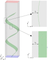
Figure 1.
Figure 1.
Conceptual collar–vane–flagellum model. Flagellar vane (green) inside a sealed collar of 3.1 µm square cross section and height 13.2 µm (grey) with inlet (blue), outlet (red) and defined gaps s1 and s2 for flow leaks between the beating flagellum edges and the collar. (Online version in colour.)
Figure 2.
Figure 2.
Choanocyte chamber and model. (a) Scanning electron microscope (SEM) image of the choanocyte chamber of the freshwater sponge Spongilla lacustris. Choanocyte (Ch), microvilli (MV) of collars, flagellum with vane (F), ends of collars (C) connected to the secondary reticulum (*). Reproduced with permission from [11] (license no. 4464811172505). (b) Schematic of a unit section of the choanocyte chamber holding one choanocyte. Cell (c); flagellum (fl); collar, open near cell (oc), sealed by glycocalyx mesh above (sc), and connected to other collars at distal ends by a sealed secondary reticulum (R2) bounding the high-pressure zone (hi). Arrows show inflow from the incurrent canal system through the prosopyle (pr) to the low-pressure zone (lo) bounded by the primary reticulum (R1) and through the opening at the collar base (oc). Stippled lines represent the surface between adjacent similar domains, each with one choanocyte. The flow from the many (50–80) choanocytes in the chamber leaves the high-pressure zone through a single outlet, the apopyle (not shown), leading to the excurrent canal system. (c) Choanocyte model used in the CFD study where different boundary conditions (table 1) are imposed on surfaces between adjacent choanocytes to simulate possible interactions between neighbouring choanocytes. The computational domain consists of a 3.1 µm square by 8.2 µm high collar centred in a 9 µm square by 13.2 µm high outer domain with a semi-circular prosopyle inlet of diameter 5 µm at lower right. (Online version in colour.)
Figure 3.
Figure 3.
Effect of gap widths s1 and s2 on the maximum pressure delivered by the flagellum–vane–collar system (figure 1) under the ’shut-off’ condition of closed inlet and outlet. Equation (2.8) (dashed curves) fits well the CFD results (symbols). The pressure rise highly depends on the gap sizes and thus on the flagellum–collar interaction.
Figure 4.
Figure 4.
Modelled pump characteristic (Ppump, obtained from equation (2.13) with C1 = 0, dashed) minus estimated system characteristic (Ps, equation (3.1), dashed-dot) gives resulting back-pressure characteristic (Pb, solid) in good agreement with experimental data (symbols). *[7, fig. 1c].
Figure 5.
Figure 5.
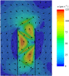
Velocity fields in the choanocyte model (figure 2c) with (a) and without (b) the presence of the glycocalyx mesh on the distal two-thirds length of the collar, for the case of an imposed canal system pressure loss of Pch = 1 mmH2O. With the mesh, the flow enters the collar at its base, and, after its pressure increases inside the sealed part of the collar, it leaves the collar toward the apopyle. Without the mesh, some flow leaks out through the distal part of the collar, reducing the net pumping rate as seen from the reduced inflow through the prosopyle at the lower right (see also figure 6). The colour bar and arrows (constant length) show the magnitude and direction of the velocity field, respectively. (Online version in colour.)
Figure 6.
Figure 6.
Volume flow rate (Q) versus permeability of the collar for different values of imposed canal system pressure loss Pch (mmH2O). For Pch = 0, the volume flow rate is constant. For increasing values of imposed system pressure loss, the fine glycocalyx mesh is essential for the pump to deliver the required flow rate.
Figure 7.
Figure 7.
Velocity field in the choanocyte model of Spongilla lacustris without the secondary reticulum (R2 of figure 2c) for no imposed system pressure loss (Pch = 0). While the flow through the collar exit is nearly the same as with the reticulum (Q ∼ 453 µm3 s−1) the net flow rate leaving the choanocyte model is very low (Q = 60 µm3 s−1) because the pressure provided by the flagellum drives a strong backflow from the exit of the collar to its base as there is no reticulum to stop this. The colour bar and arrows (constant length) show the magnitude and direction of the velocity field, respectively. (Online version in colour.)

References

    1. Jørgensen CB. 1966. Biology of suspension feeding. Oxford, UK: Pergamon Press.
    1. Riisgård HU, Larsen PS. 1995. Filter-feeding in marine macro-invertebrates: pump characteristics, modelling and energy cost. Biol. Rev. 70, 67–106. ( 10.1111/j.1469-185X.1995.tb01440.x) - DOI - PubMed
    1. Riisgård HU, Kumala L, Charitonidou K. 2016. Using the F/R-ratio for an evaluation of the ability of the demosponge Halichondria panicea to nourish solely on phytoplankton versus free-living bacteria in the sea. Mar. Biol. Res. 12, 907–916. ( 10.1080/17451000.2016.1206941) - DOI
    1. Ludeman DA, Reidenbach MA, Leys SP. 2017. The energetic cost of filtration by demosponges and their behavioural response to ambient currents. J. Exp. Biol. 220, 995–1007. ( 10.1242/jeb.146076) - DOI - PubMed
    1. Reiswig HM. 1971. In situ pumping activities of tropical demospongiae. Mar. Biol. 9, 38–50. ( 10.1007/BF00348816) - DOI

Publication types

LinkOut - more resources