Review
. 2019 Jan 15;11(1):143.
doi: 10.3390/polym11010143.

The Applications of Polymers in Solar Cells: A Review

Affiliations
Review

The Applications of Polymers in Solar Cells: A Review

Wenjing Hou et al. Polymers (Basel). .

Abstract

The emerging dye-sensitized solar cells, perovskite solar cells, and organic solar cells have been regarded as promising photovoltaic technologies. The device structures and components of these solar cells are imperative to the device's efficiency and stability. Polymers can be used to adjust the device components and structures of these solar cells purposefully, due to their diversified properties. In dye-sensitized solar cells, polymers can be used as flexible substrates, pore- and film-forming agents of photoanode films, platinum-free counter electrodes, and the frameworks of quasi-solid-state electrolytes. In perovskite solar cells, polymers can be used as the additives to adjust the nucleation and crystallization processes in perovskite films. The polymers can also be used as hole transfer materials, electron transfer materials, and interface layer to enhance the carrier separation efficiency and reduce the recombination. In organic solar cells, polymers are often used as donor layers, buffer layers, and other polymer-based micro/nanostructures in binary or ternary devices to influence device performances. The current achievements about the applications of polymers in solar cells are reviewed and analyzed. In addition, the benefits of polymers for solar cells, the challenges for practical application, and possible solutions are also assessed.

Keywords: applications; polymers; solar cells.


Conflict of interest statement

The authors declare no conflict of interest.

Figures

Figure 1
Figure 1
Photoelectric conversion efficiencies for various photovoltaic technologies since 1976 by National Renewable Energy Laboratory (NREL) [15].
Figure 2
Figure 2
Fundamental processes of dye-sensitized solar cells (Reproduced from Reference [32] with permission, copyright The Royal Society of Chemistry, 2017).
Figure 3
Figure 3
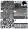
Field Emission Scanning Electron Microscope (FESEM) images and corresponding cross-sectional FESEM images of different conductive polymers counter electrodes: (a,b) Paper-like PPy membrane (reproduced from Reference [76] with permission, copyright American Chemical Society, 2014); (c,d) polyaniline (PANI) nanoribbons (reproduced from Reference [83] with permission, copyright Elsevier, 2016); and (e,f) PEDOT nanotubes (reproduced from Reference [93] with permission, copyright Wiley, 2011), respectively.
Figure 4
Figure 4
FESEM images of different hybrids counter electrodes based on conductive polymers: (a) PPy/MWCNT (reproduced from Reference [101] with permission, copyright Elsevier, 2016); (b) TiN particles-PEDOT:PSS (reproduced from Reference [102] with permission, copyright American Chemical Society, 2012); and (c) RGO/PPy/PEDOT composites (reproduced from Reference [104] with permission, copyright Elsevier, 2015), respectively.
Figure 5
Figure 5
(a) Preparation schematic of PS nanobeads on FTO/Pt substrate; (b) Comparison schematic of the pore-filling before (left) and after (right) dissolving the PS nanobeads; (c and d) FESEM images and photographs of the PS nanobeads on the FTO/Pt substrate before (left) and after (right) the dissolution process; (e) Conversion schematic of liquid electrolyte to gel electrolyte by using valeronitrile solvent to dissolve the PS nanobeads (reproduced from Reference [123] with permission, copyright American Chemical Society, 2012).
Figure 6
Figure 6
Photographs of thermosetting polymer electrolyte (PAA-PEG/NMP + GBL/NaI + I2): (a) Before and (b) after soaking in I3/I liquid electrolyte, respectively (reproduced from Reference [129] with permission, copyright Wiley, 2007).
Figure 7
Figure 7
Upside-down vessel containing the PMII/I2/PEGDME electrolyte with (a) none, (b) 9 wt % of fumed silica, (c) 9 wt % of silica rods, and (d)12 wt % of silica rods, respectively (reproduced from Reference [132] with permission, copyright American Chemical Society, 2014).
Figure 8
Figure 8
Schematic diagram of energy levels arrangement in perovskite solar cells (reproduced from Reference [145] with permission, copyright Nature Publishing Group, 2014).
Figure 9
Figure 9
Molecular structures of common polymer additives.
Figure 10
Figure 10
Comparisons of FESEM images and corresponding cross-sectional FESEM images of perovskite films with and without several different polymer additives: (a) PEI (reproduced from Reference [165] with permission, copyright The Royal Society of Chemistry, 2016), (b) PVP (reproduced from Reference [166] with permission, copyright Wiley, 2017), (c) PEG (reproduced from Reference [170] with permission, copyright American Chemical Society, 2015), and (d) PMMA (reproduced from Reference [173] with permission, copyright Nature Publishing Group, 2014), respectively.
Figure 11
Figure 11
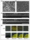
Comparisons of FESEM and corresponding cross-sectional FESEM images of perovskite films: (a,c) With PEG, and (b,d) without PEG, respectively. (e) Photographs of the color change of perovskite films with and without PEG after water-spraying for 60 s and kept in ambient air for 45 s (reproduced from Reference [171] with permission, copyright Nature Publishing Group, 2016).
Figure 12
Figure 12
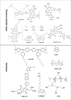
Chemical structures of polymers used to discuss the hole transport materials.
Figure 13
Figure 13
Visible degradation photographs of perovskite films covered with different hole transport materials, including the Li-spiro-OMeTAD, P3HT, PTAA, PMMA and P3HT/SWNT-PMMA (reproduced from Reference [211] with permission, copyright American Chemical Society, 2014).
Figure 14
Figure 14
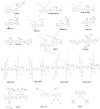
Chemical structures of polymers used to discuss the electron transport layers and interlayers.
Figure 15
Figure 15
Mechanism diagram of organic photovoltaics (reproduced from Reference [230] with permission, copyright Wiley, 2014).
Figure 16
Figure 16
Molecular structures of materials for photoactive layers.
Figure 17
Figure 17
(a) Molecular structures of PBDB-T, F-M, PTB7-Th, O6T-4F and PC71BM; (b) Normalized absorption spectra of PBDB-T:F-M and PTB7-Th:O6T-4F:PC71BM films; (c) and (d) Device architecture and energy level diagram of the tandem cell, respectively (reproduced from Reference [264] with permission, copyright Science, 2018).

References

    1. Sovacool B.K. National context derives concrens. Nat. Energy. 2018 doi: 10.1038/s41560-018-0246-5. - DOI
    1. Quirin S., Jeff T., Tony S., Alexandra W., Oliver M. Energy alternatives: Electricity without carbon. Nature. 2008;454:816–823. doi: 10.1038/454816a. - DOI - PubMed
    1. Green M.A. The path to 25% silicon solar cell efficiency: History of silicon cell evolution. Prog. Photovolt Res. Appl. 2009;17:183–189. doi: 10.1002/pip.892. - DOI
    1. Razykov T.M., Ferekides C.S., Morel D., Stefanakos E., Ullal H.S., Upadhyaya H.M. Solar photovoltaic electricity: Current status and future prospects. Sol. Energy. 2011;85:1580–1608. doi: 10.1016/j.solener.2010.12.002. - DOI
    1. Hubbard S.M., Cress C.D., Bailey C.G., Raffaelle R.P., Bailey S.G., Wilt D.M. Effect of strain compensation on quantum dot enhanced GaAs solar cells. Appl. Phys. Lett. 2008;92:123512. doi: 10.1063/1.2903699. - DOI

LinkOut - more resources