. 2017 Dec 8;9(12):690.
doi: 10.3390/polym9120690.

Plateau-Shaped Flexible Polymer Microelectrode Array for Neural Recording

Affiliations

Plateau-Shaped Flexible Polymer Microelectrode Array for Neural Recording

Jun-Min Kim et al. Polymers (Basel). .

Abstract

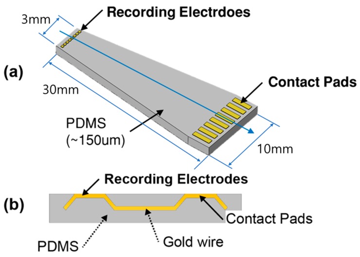
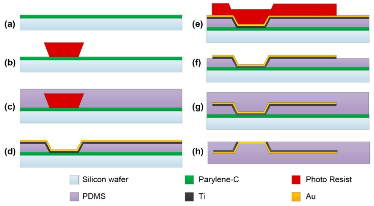
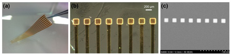
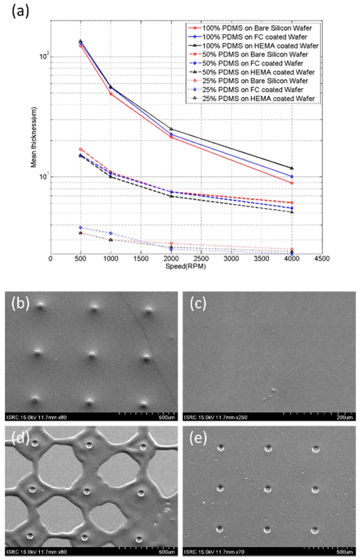
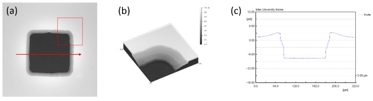
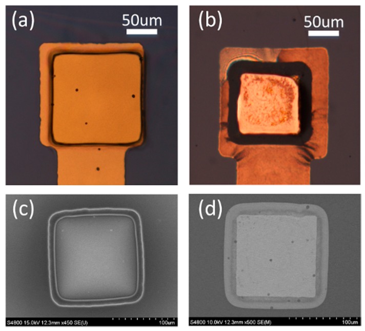
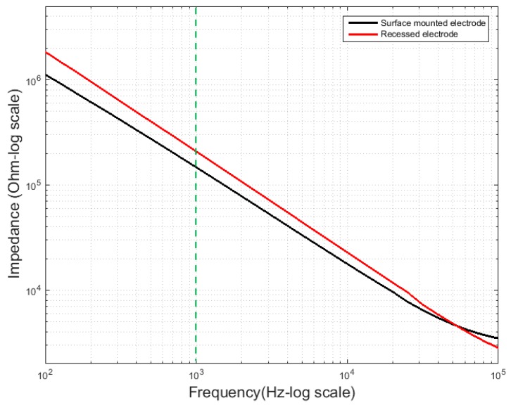
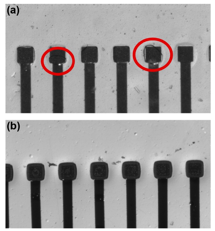
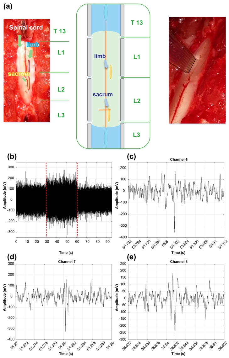
Conventional polymer multielectrode arrays (MEAs) have limitations resulting from a high Young's modulus, including low conformability and gaps between the electrodes and neurons. These gaps are not a problem in soft tissues such as the brain, due to the repopulation phenomenon. However, gaps can result in signal degradation when recording from a fiber bundle, such as the spinal cord. Methods: We propose a method for fabricating flexible polydimethylsiloxane (PDMS)-based MEAs featuring plateau-shaped microelectrodes. The proposed fabrication technique enables the electrodes on the surface of MEAs to make a tight connection to the neurons, because the wire of the MEA is fabricated to be plateau-shaped, as the Young's modulus of PDMS is similar to soft tissues and PDMS follows the curvature of the neural tissue due to its high conformability compared to the other polymers. Injury caused by the movement of the MEAs can therefore be minimized. Each electrode has a diameter of 130 μm and the 8-channel array has a center-to-center electrode spacing of 300 μm. The signal-to-noise ratio of the plateau-shaped electrodes was larger than that of recessed electrodes because there was no space between the electrode and neural cell. Reliable neural recordings were possible by adjusting the position of the electrode during the experiment without trapping air under the electrodes. Simultaneous multi-channel neural recordings were successfully achieved from the spinal cord of rodents. We describe the fabrication technique, electrode 3D profile, electrode impedance, and MEA performance in in vivo experiments in rodents.

Keywords: PDMS; PDMS etching; fabrication; multielectrode array (MEA); plateau-shaped electrode; recessed electrode; spinal cord signal recording; underexposure.


Conflict of interest statement

The authors declare no conflict of interest.

Figures

Figure 1
Figure 1
3D schematic of the electrode array. (a) Schematic of a polydimethylsiloxane (PDMS)-based multielectrode array. (b) Cross-section along the blue arrowed line in (a).
Figure 2
Figure 2
Schematic of fabrication process for a PDMS-based plateau electrode array.
Figure 3
Figure 3
Images of fabricated PDMS-based plateau MEA. (a) The overall appearance of the MEA. The sacrificial photoresist post of this sample was spin-coated twice at 1300 rpm for 20 s. The thickness was 20 μm and the depth of the PDMS hole was 11 μm. (b) Optical microscope image of the plateau microelectrodes. The bright region around the electrode is the gold film on the wall of the PDMS hole. (c) SEM image of the plateau microelectrodes. As the gold wires are inside the PDMS, we could not observe them using SEM. The electrodes were deposited with dimensions of 100 μm × 100 μm, but the SEM measurements show dimensions of 130 μm × 130 μm. The increase in electrode size is caused by the addition of the 160 μm PET film and the shrinking and etching of PDMS as a result of the NMP and TBAF solutions.
Figure 4
Figure 4
SEM images of the inclined sacrificial post under different exposure conditions. The height of the photoresist post was 20 μm, and the pattern of the photomask was a circle with a diameter of 50 μm. (a) A 160 μm PET film was placed between the wafer and photomask, and the exposure time was 14 s at 25 mW/cm2. The angle of the resulting post was 50°, obtained by averaging 9 individual posts from five rounds of fabrication. (b) The same PET film was used, with an exposure time of 14 s. The measured angle was 63°. (c) Soft contact was used, the exposure time was 14 s, and the angle was 72°. (d) Hard contact was used, the exposure time was 14 s, and the angle was 83°.
Figure 5
Figure 5
Characterization of PDMS spin-coating. (a) The thickness of PDMS film depended on spin-coating speed. The spin-coating speeds were 500, 1000, 2000, and 4000 rpm for 60 s. Each point on the plot corresponds to measurements on 25 samples from 5 rounds of fabrication. (be) SEM images measuring the uniformity of the PDMS film. (b) Uncured PDMS spin-coated with a thickness of 10 μm on a photoresist post with a height of 20 μm. (c) Uncured PDMS spin-coated with a thickness of 40 μm on a photoresist post with a height of 20 μm. The photoresist posts are not revealed on the surface due to the thick PDMS film. (d) Cured PDMS of (b) etched by 9% TBAF solution for 4 min. The PDMS in the nearby and far posts were thick and thin, respectively. Hence, we could not obtain a uniform PDMS film. (e) Cured PDMS of (b) etched by 9% TBAF solution for 10 min. Uniform PDMS film with holes could be obtained.
Figure 6
Figure 6
3D rear profile images of plateau electrodes. (a,b) Wide field optical microscope images of an electrode. (a) The gray rectangle band shows the slope of the electrode. (b) An enlarged 3D projection of the region in the red rectangle of the image in (a). We can observe the gently sloping PDMS wall, which has an inclination angle of 40°. (c) 2D profile of the electrode obtained along the red line in (a). One side of the electrode is approximately 130 μm, and the depth of the electrode is approximately 11 μm.
Figure 7
Figure 7
Optical and SEM images of a recessed electrode and a plateau electrode. (a) Enlarged image of the recessed electrode obtained using an optical microscope. Metal wires can be seen to pass under the PDMS film. (b) Plateau electrode. The dark band shows the PDMS slope connecting the electrode and wire. (c) SEM image of recessed electrode. The inclined holes can be observed on the PDMS film. (d) SEM image of plateau electrode.
Figure 8
Figure 8
Electrode impedance measurement. Five measurements of electrode impedance on the eight individual electrodes of 10 MEAs are considered. The average electrode impedance curves rely on the electrode area and depth.
Figure 9
Figure 9
Optical microscope images for surface contact performance of plateau electrode. (a) An air bubble is trapped in the recessed electrode due to the hydrophobicity of the PDMS surface. (b) As there is no gap between the slide glass and electrodes, air bubbles are not seen on plateau electrodes.
Figure 10
Figure 10
In vivo experiment. (a) In vivo placement of a PDMS-based MEA on a rat spinal cord. (b) Raw data from Channel 7. The period of the stimulus is indicated by the red dotted-lines. (c) An SSEPR from Channel 6. (d) An SSEPR from Channel 7. (e) An SSEPR from Channel 8.

References

    1. Aravanis A.M., Wang L.P., Zhang F., Meltzer L.A., Mogri M.Z., Schneider M.B., Deisseroth K. An optical neural interface: In vivo control of rodent motor cortex with integrated fiberoptic and optogenetic technology. J. Neural Eng. 2007;4:S143–S156. doi: 10.1088/1741-2560/4/3/S02. - DOI - PubMed
    1. Donoghue J.P., Nurmikko A., Black M., Hochberg L.R. Assistive technology and robotic control using motor cortex ensemble-based neural interface systems in humans with tetraplegia. J. Physiol. 2007;579:603–611. doi: 10.1113/jphysiol.2006.127209. - DOI - PMC - PubMed
    1. Donoghue J.P. Bridging the Brain to the World: A Perspective on Neural Interface Systems. Neuron. 2008;60:511–521. doi: 10.1016/j.neuron.2008.10.037. - DOI - PubMed
    1. Disselhorst-Klug C., Bahm J., Ramaekers V., Trachterna A., Rau G. Non-invasive approach of motor unit recording during muscle contractions in humans. Eur. J. Appl. Physiol. 2000;83:144–150. doi: 10.1007/s004210000272. - DOI - PubMed
    1. Reucher H., Rau G., Silny J. Spatial Filtering of Noninvasive Multielectrode EMG: Part I-Introduction to Measuring Technique and Applications. IEEE Trans. Biomed. Eng. 1987;BME-34:98–105. doi: 10.1109/TBME.1987.326034. - DOI - PubMed

LinkOut - more resources