Review
. 2017 Feb 16;9(2):67.
doi: 10.3390/polym9020067.

Polymers in Carbon Dots: A Review

Affiliations
Review

Polymers in Carbon Dots: A Review

Yiqun Zhou et al. Polymers (Basel). .

Abstract

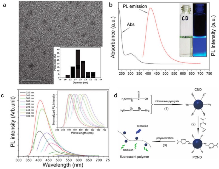
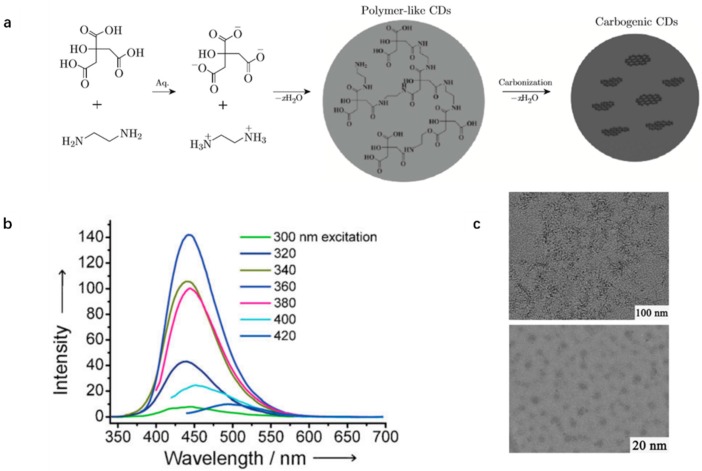
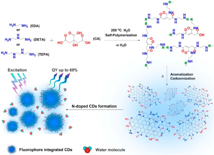
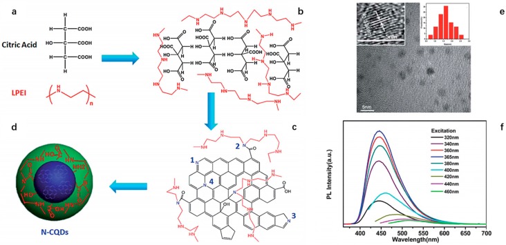
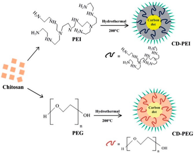
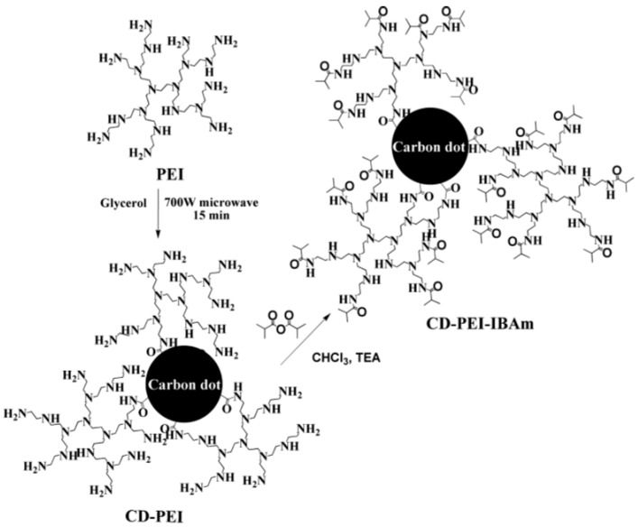
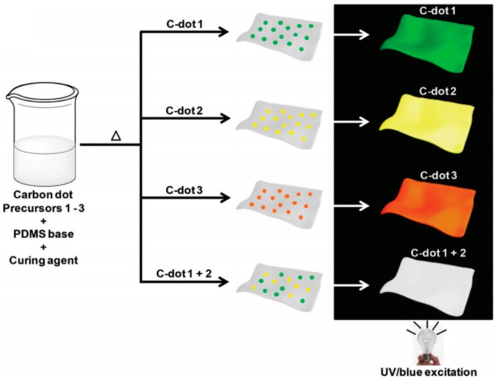
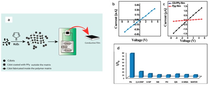
Carbon dots (CDs) have been widely studied since their discovery in 2004 as a green substitute of the traditional quantum dots due to their excellent photoluminescence (PL) and high biocompatibility. Meanwhile, polymers have increasingly become an important component for both synthesis and modification of CDs to provide polymeric matrix and enhance their PL property. Furthermore, critical analysis of composites of CDs and polymers has not been available. Herein, in this review, we summarized the use of polymers in the synthesis and functionalization of CDs, and the applications of these CDs in various fields.

Keywords: carbon dots; composites; polymerization; polymers; surface modification.


Conflict of interest statement

The authors declare no conflict of interest.

Figures

Figure 1
Figure 1
(a) The molecular structure of lignin; (b) TEM and (c) HRTEM images of CDs; (d) a confocal fluorescence microphotograph of Hela cells labeled with the CDs (λ ex: 405 nm); (e) a bright field microphotograph of the cells; and (f) an overlay image of (d,e). Figure adapted from Ref. [42] with permissions from the publishers.
Figure 2
Figure 2
(a) Processing diagram for the synthesis of photoluminescent CDs; and (b) HRTEM image of CDs passivated with PEG1500N. The inset is the SAED pattern. Figure adapted from Ref. [48] with permissions from the publishers.
Figure 3
Figure 3
(a) Monomers and the molar ratios used in the synthesis of P1–P5; (b) aqueous solutions of CDs CD-P1 to CD-P5 (0.1% w/v) excited at 365 nm; and (c) PL spectra of CD-P1 to CD-P5 (λ ex 400 nm). Figure adapted from Ref. [54] with permissions from the publishers.
Figure 4
Figure 4
Illustration of the preparation of photoluminescent CDs: (a) indicates the synthesis of P(MA-r-EDY); (b) means deprotection of trimethylsilyl groups; (c) shows the formation of polymeric nanoparticles; (d) indicates the carbonization of the polymeric nanoparticles; (e) means the formation of CDs with passivated surface state; and (f) demonstrates functionalization of CDs surface. Figure adapted from Ref. [47] with permissions from the publishers.
Figure 5
Figure 5
(a) HRTEM image of CNDs (scale bar: 10 nm) with a narrow size distribution of 2.0–3.2 nm in diameter; (b) UV/Vis spectrum (λab = 300 nm) and PL emission spectrum (λex = 360 nm) of an aqueous solution of the CNDs (1 mg·mL−1) with an emission peak at 420 nm; (c) PL emission spectra of the CNDs aqueous solution under excitation with different wavelengths (inset is the normalized PL emission spectra); and (d) synthesis procedure of: CNDs (1); PCNDs (2); and fluorescent polymers (3). Figure adapted from Ref. [57] with permissions from the publishers.
Figure 6
Figure 6
(a) Reaction mechanism of CDs synthesized by CA and EDA; (b) excitation-dependent PL spectra of CDs; and (c) TEM (upper) and HRTEM (lower) images of CDs. Figure adapted from Ref. [61] with permissions from the publishers.
Figure 7
Figure 7
Proposed formation pathway of N-doped CDs. Figure adapted from Ref. [56] with permissions from the publishers.
Figure 8
Figure 8
Proposed formation pathway, composition, and structures of as-obtained N-CDs: (a) polymerization of final N-CDs; (b,c) incorporation of N atom to final N-CDs (1, 3, and 4 indicate N atom existing in the aromatic framework and 2 shows LPEI linked to N-CDs by formation of amide groups); (d) surface passivation of N-CDs by –COOH, –OH, amine groups and LPEI chains; (e) TEM image of N-CDs (inset, HRTEM image and size distribution of 1–3 nm in diameter with 1.67 nm on average); and (f) PL spectra under excitation wavelength shorter than 500 nm. Figure adapted from Ref. [58] with permissions from the publishers.
Figure 9
Figure 9
Schematic diagram depicting one-pot hydrothermal synthesis of CD-PEI and CD-PEG. Figure adapted from Ref. [88] with permissions from the publishers.
Figure 10
Figure 10
Preparation of Multi Stimuli-Responsive CDs. Figure adapted from Ref. [89] with permissions from the publishers.
Figure 11
Figure 11
Phtoluminescent C-dot/PDMS films. Scheme describing the preparation of the mixed films. Distinct-colored C-dots embedded in the films were prepared by using different precursors. C-dot 1–3 indicates the carbon precursor is 6-O-(O-O′-Di-lauroyl-tartaryl)-d-glucose, 6-O-(O-O′-Di-lauroyl-tartaryl)-l-ascorbic acid, and Vitamin B1 + oleic acid, respectively. Figure adapted from Ref. [40] with permissions from the publishers.
Figure 12
Figure 12
(a) Schematic representation of the synthesis of CDs-PPy composite and the primary set up for the conductivity experiment of the picric acid. Plot of IV characteristics of: (b) CDs film; and (c) CD-PPy film and PPy film. (d) The ratios of current flowing through the composite film after adding 2.0 μL 1.0 mM aqueous solution of different analytes to that of the film only. Here PA = picric acid, 2,4-DNP = 2,4-dinitrophenol, 4-NP = 4-nitrophenol, NB = nitrobenzene, PH = phenol, QN = 1,4-benzoquinone, 4-MBA = 4-methoxybenzoic acid. The measurements were made at +5 V. Figure adapted from Ref. [108] with permissions from the publishers.

References

    1. Suri S.S., Fenniri H., Singh B. Nanotechnology-based drug delivery systems. J. Occup. Med. Toxicol. 2007;2:16–21. doi: 10.1186/1745-6673-2-16. - DOI - PMC - PubMed
    1. Schulte J. Nanotechnology in environmental protection and pollution sustainable future, environmental cleanup and energy solutions. Sci. Technol. Adv. Mater. 2007;8:11. doi: 10.1016/j.stam.2006.11.019. - DOI
    1. Yang Y., Zheng Y., Cao W., Titov A., Hyvonen J., MandersJesse R., Xue J., Holloway P.H., Qian L. High-efficiency light-emitting devices based on quantum dots with tailored nanostructures. Nat. Photonics. 2015;9:259–266. doi: 10.1038/nphoton.2015.36. - DOI
    1. Prober D.E. Instrumentation: Astronomers look to nanotechnology. Nat. Nanotechnol. 2008;3:459–460. doi: 10.1038/nnano.2008.221. - DOI - PubMed
    1. Mo Y.-M., Tang Y., Gao F., Yang J., Zhang Y.-M. Synthesis of fluorescent CdS quantum dots of tunable light emission with a new in situ produced capping agent. Ind. Eng. Chem. Res. 2012;51:5995–6000. doi: 10.1021/ie201826e. - DOI

LinkOut - more resources