. 2018:7:230-244.
doi: 10.1109/ACCESS.2018.2885336. Epub 2018 Dec 7.

A Programmable Multi-biomarker Neural Sensor for Closed-loop DBS

Affiliations

A Programmable Multi-biomarker Neural Sensor for Closed-loop DBS

Mahboubeh Parastarfeizabadi et al. IEEE Access. 2018.

Abstract

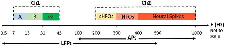
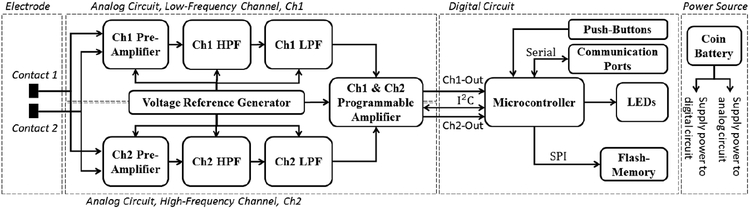
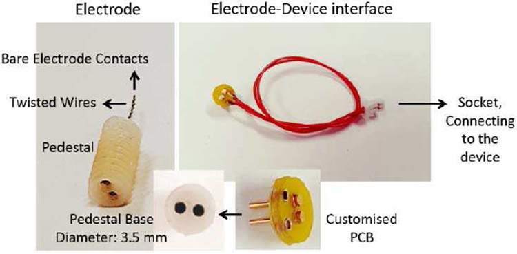
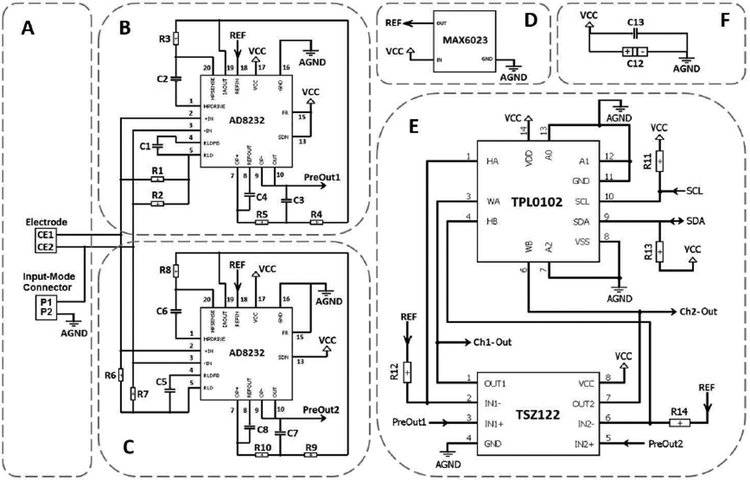
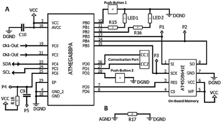
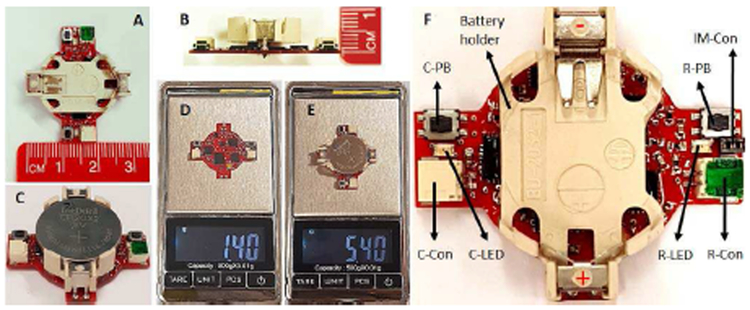
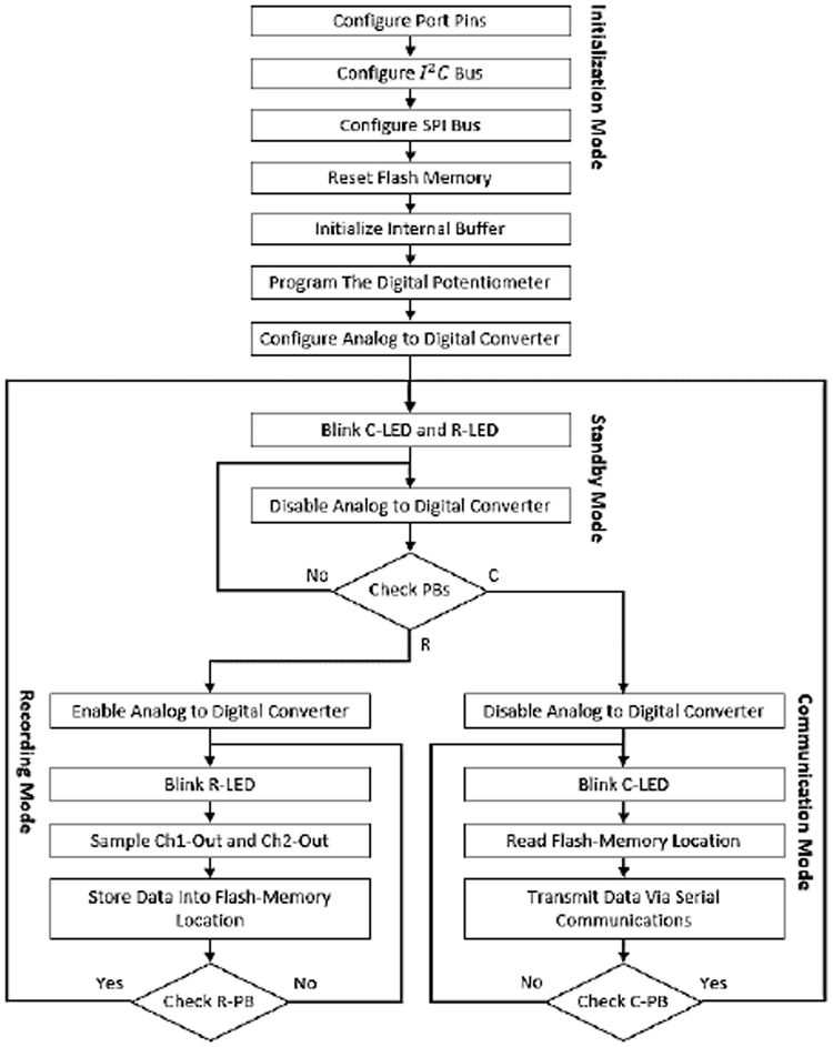
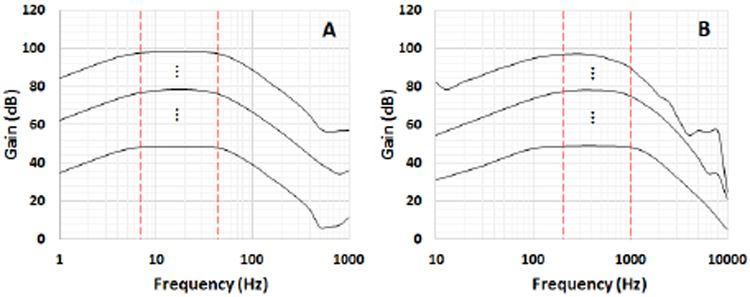
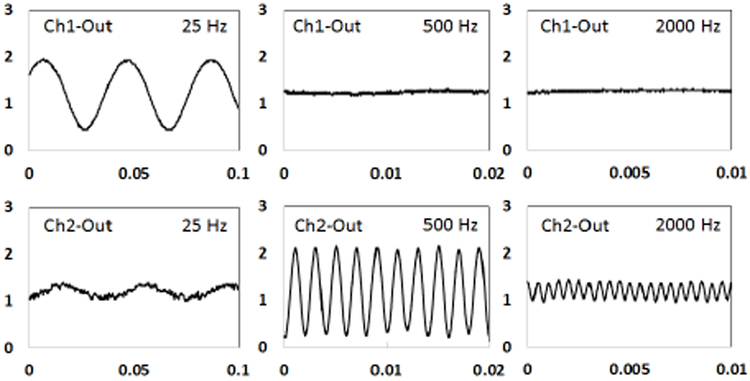
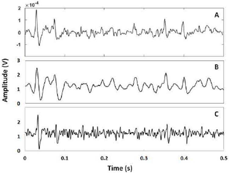
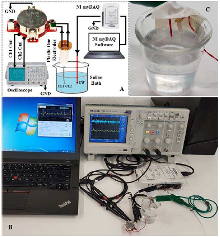
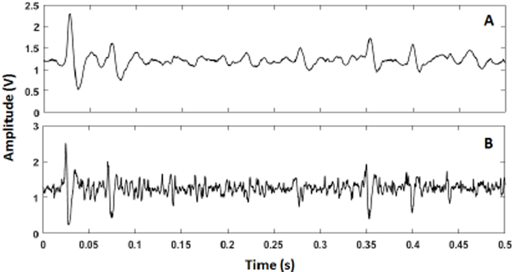
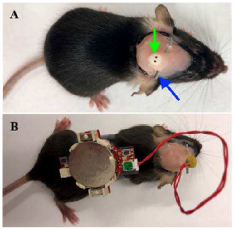
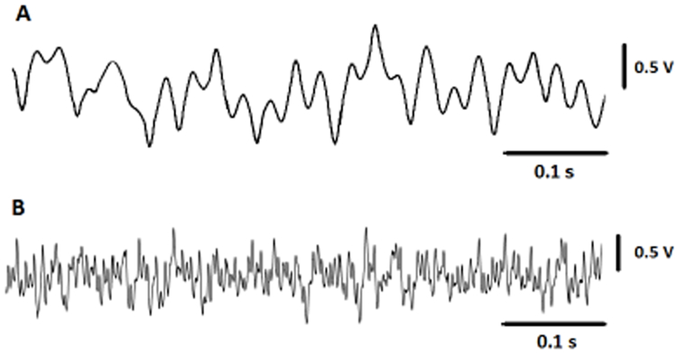
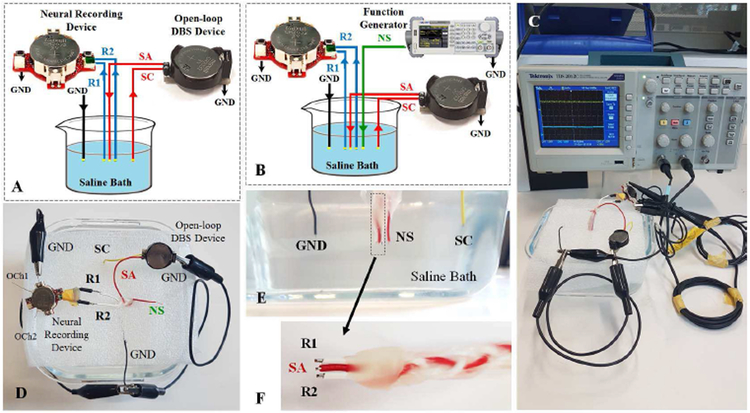
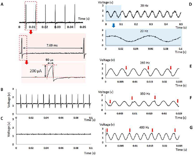
Most of the current closed-loop DBS devices use a single biomarker in their feedback loop which may limit their performance and applications. This paper presents design, fabrication, and validation of a programmable multi-biomarker neural sensor which can be integrated into closed-loop DBS devices. The device is capable of sensing a combination of low-frequency (7-45 Hz), and high-frequency (200-1000 Hz) neural signals. The signals can be amplified with a digitally programmable gain within the range 50-100 dB. The neural signals can be stored into a local memory for processing and validation. The sensing and storage functions are implemented via a combination of analog and digital circuits involving preamplifiers, filters, programmable post-amplifiers, microcontroller, digital potentiometer, and flash memory. The device is fabricated, and its performance is validated through: (i) bench tests using sinusoidal and pre-recorded neural signals, (ii) in-vitro tests using pre-recorded neural signals in saline solution, and (iii) in-vivo tests by recording neural signals from freely-moving laboratory mice. The animals were implanted with a PlasticsOne electrode, and recording was conducted after recovery from the electrode implantation surgery. The experimental results are presented and discussed confirming the successful operation of the device. The size and weight of the device enable tetherless back-mountable use in pre-clinical trials.

Keywords: Circuits; Closed-loop; Multiple Biomarkers; Neural sensor; Programmable.


Figures

Fig. 1.
Fig. 1.
Frequency specifications of the biomarkers recorded using the neural sensor. A: Alpha, B: Beta, sG: slow gamma, sHFO: slow high-frequency oscillations, fHFO: fast high-frequency oscillations, Ch1: channel 1, Ch2: channel 2, F: Frequency.
Fig. 2.
Fig. 2.
Overview of the programmable multi-biomarker neural sensor.
Fig. 3.
Fig. 3.
PlasticsOne electrode, and customized electrode-device interface.
Fig. 4.
Fig. 4.
Schematic diagram of the analog circuit. (A) Electrode and Input-mode connector mechanism. (B) Pre-amplifier, low-pass and high-pass filters for Channel 1. (C) Pre-amplifier, low-pass and high-pass filters for Channel 2. (D) Voltage reference generator. (E) Programmable amplifier for both Channels 1 and 2. (F) By-pass noise-reduction capacitors.
Fig. 5.
Fig. 5.
Schematic diagram of the digital circuit. (A) Digital circuit. (B) Analog and digital ground separation.
Fig. 6.
Fig. 6.
(A) & (B) Device dimensions. (C) Complete device. (D) Weight of the device without the battery and battery holder. (E) Total weight of the complete device. (F) Operation features. C-PB: communication pushbutton, R-PB: recording push-button, C-Con: communication connector, RCon: recording connector, C-LED: communication LED, R-LED: recording LED, IM-Con: input-mode connector.
Fig. 7.
Fig. 7.
Schematic diagram of the digital circuit. (A) Digital circuit. (B) Analog and digital ground separation.
Fig. 8.
Fig. 8.
Frequency response of the low-frequency (A) and high- frequency (B) channels.
Fig. 9.
Fig. 9.
Analog outputs resulted from a sinusoidal input signal (200 μVpp) with three different frequencies (25 Hz, 500 Hz, and 2000 Hz). The gain of was set to 78 dB. Values on the vertical axis represent the output amplitude in volt. Values on the horizontal axis resent time in in seconds.
Fig. 10.
Fig. 10.
(A) Pre-recorded neural signal applied directly to the device in a single-ended configuration. (B) Ch1 output. (C) Ch2 output.
Fig. 11.
Fig. 11.
(A) Saline-based in-vitro setup model used to verify the Device. Ch1 and Ch2 outputs are connected to the analog output on the bottom layer of the PCB. (B) Experimental setting. (C) Electrode placement in saline solution. The red wire delivers the neural signal into the saline solution and the electrodes collects the signal in a single-ended configuration.
Fig. 12.
Fig. 12.
(A) Ch1 digital output sampled and stored in the memory from the in-vitro saline test. (B) Ch2 digital output sampled and stored in the memory from the in-vitro saline test.
Fig. 13.
Fig. 13.
Tetherless recording in adult mouse.
Fig. 14.
Fig. 14.
(A) Small portion of neural signal recorded from the cerebellum region of a mouse, sampled at Ch1, and stored into the flash-memory. (B) Small portion of neural signal recorded from the cerebellum region of a mouse, sampled at Ch2 and stored into the flash-memory.
Fig. 15.
Fig. 15.
DBS schematic test setup in (A) the presence of stimulation pulse and (B) the presence of neural signal and stimulation pulse. (C) Real DBS test setup. (D) Top view of the saline bath connections. (E) Cross section of the saline bath electrode placements. (F) Close view of the recording and stimulation copper electrodes The SA electrode is adjusted to be placed in the center of the R1 and R2 electrodes with equal distances. R1 and R2: recording electrodes, SA: stimulation anode electrode, SC: stimulation cathode electrode, GND: common ground electrode, NS: neural source signal.
Fig. 16.
Fig. 16.
(A) The specifications of the stimulation pulses generated from an open-loop DBS device to test the neural sensor performance in terms of the reaction to the DBS interference. (B) The neural sensor analog output response to the stimulation pulses in absence of the neural source in the single-ended recording configuration. (C) The neural sensor analog output response to the stimulation pulses in absence of the neural source in the differential recording configuration. (D) The neural sensor analog output in response to the DBS 130 Hz interference and a 20 Hz sinusoidal input. (E) The neural sensor analog output in response to the DBS 130 Hz interference and a 260 Hz sinusoidal input. (F) The neural sensor analog output in response to the DBS 130 Hz interference and a 350 Hz sinusoidal input. (F) The neural sensor analog output in response to the DBS 130 Hz interference and a 400 Hz sinusoidal input.

References

    1. Parastarfeizabadi M and Kouzani AZ, "Advances in closed-loop deep brain stimulation devices," Journal of NeuroEngineering and Rehabilitation, vol. 14, p. 79, August 11 2017. - PMC - PubMed
    1. Arlotti M, Rosa M, Marceglia S, Barbieri S, and Priori A, "The adaptive deep brain stimulation challenge," Parkinsonism & Related Disorders, vol. 28, pp. 12–17, 2016. - PubMed
    1. Neumann WJ, Huebl J, Brucke C, Gabriels L, Bajbouj M, Merkl A, et al. , "Different patterns of local field potentials from limbic DBS targets in patients with major depressive and obsessive compulsive disorder," Mol Psychiatry, vol. 19, pp. 1186–1192, 2014. - PMC - PubMed
    1. Thevathasan W, Pogosyan A, Hyam JA, Jenkinson N, Foltynie T, Limousin P, et al. , "Alpha oscillations in the pedunculopontine nucleus correlate with gait performance in parkinsonism," Brain, vol. 135, pp. 148–160, 2012. - PMC - PubMed
    1. Priori A, Foffani G, Pesenti A, Tamma F, Bianchi AM, Pellegrini M, et al. , "Rhythm-specific pharmacological modulation of subthalamic activity in Parkinson’s disease," Exp Neurol, vol. 189, pp. 369–79, October 2004. - PubMed

LinkOut - more resources