. 2019 Apr 4;5(4):e01454.
doi: 10.1016/j.heliyon.2019.e01454. eCollection 2019 Apr.

Non-intrusive high throughput automated data collection from the home cage

Affiliations

Non-intrusive high throughput automated data collection from the home cage

Fabio Iannello. Heliyon. .

Abstract

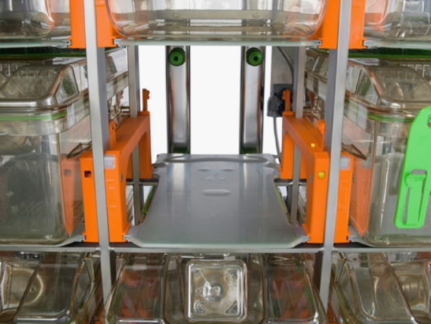
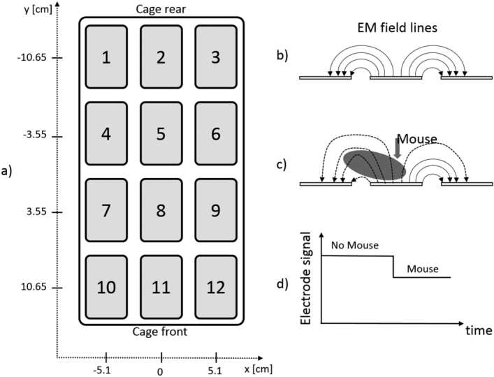
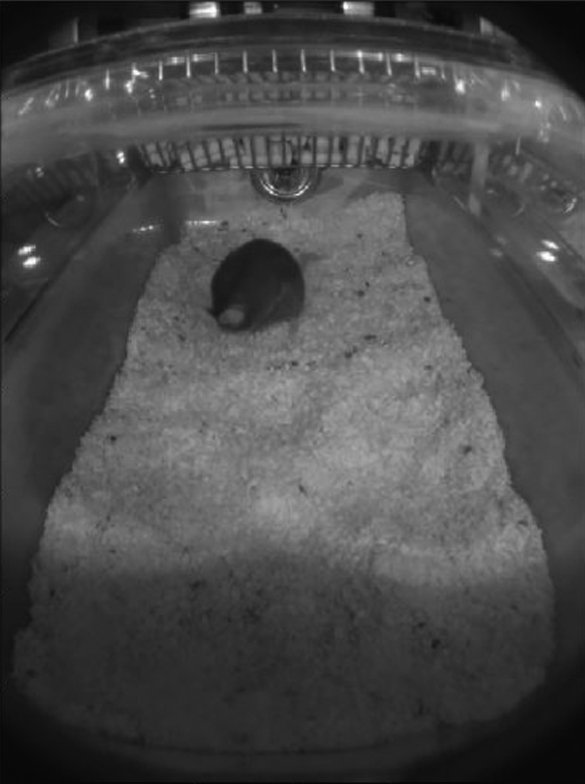
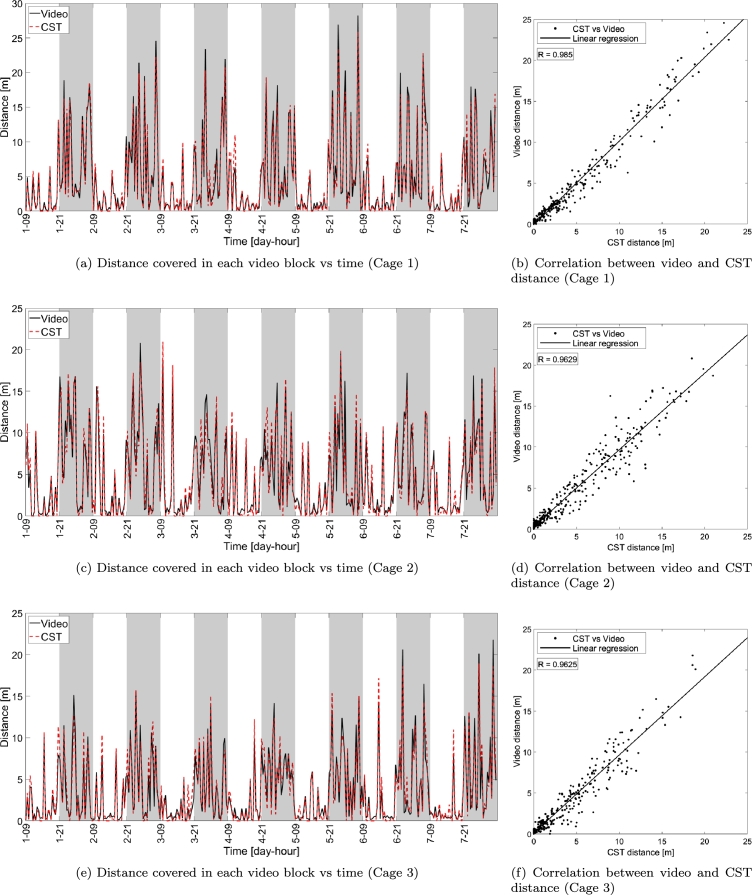
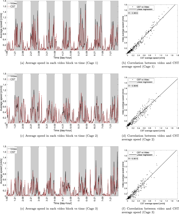
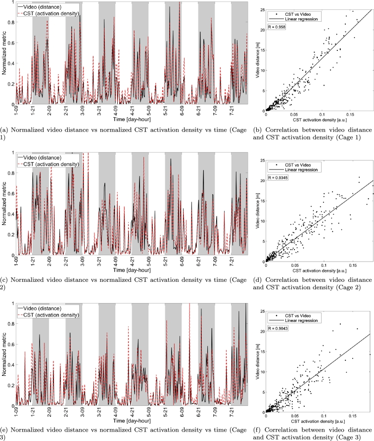
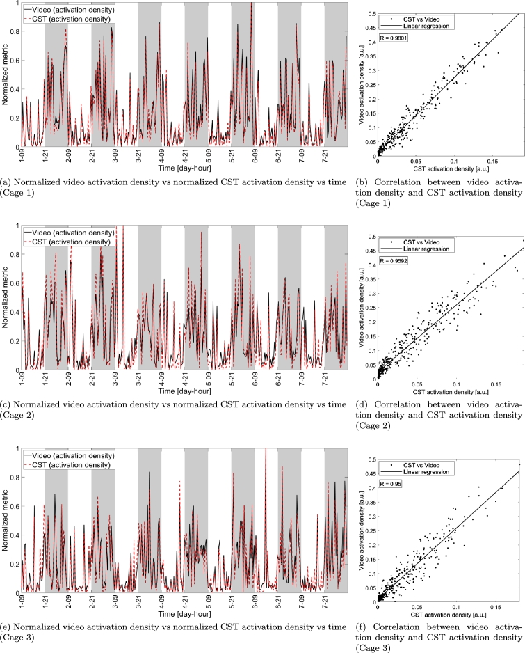
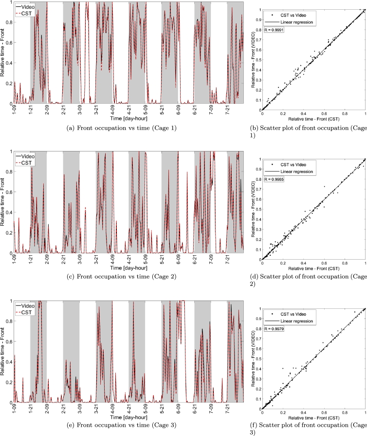
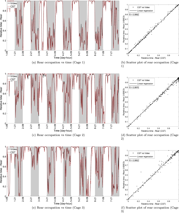
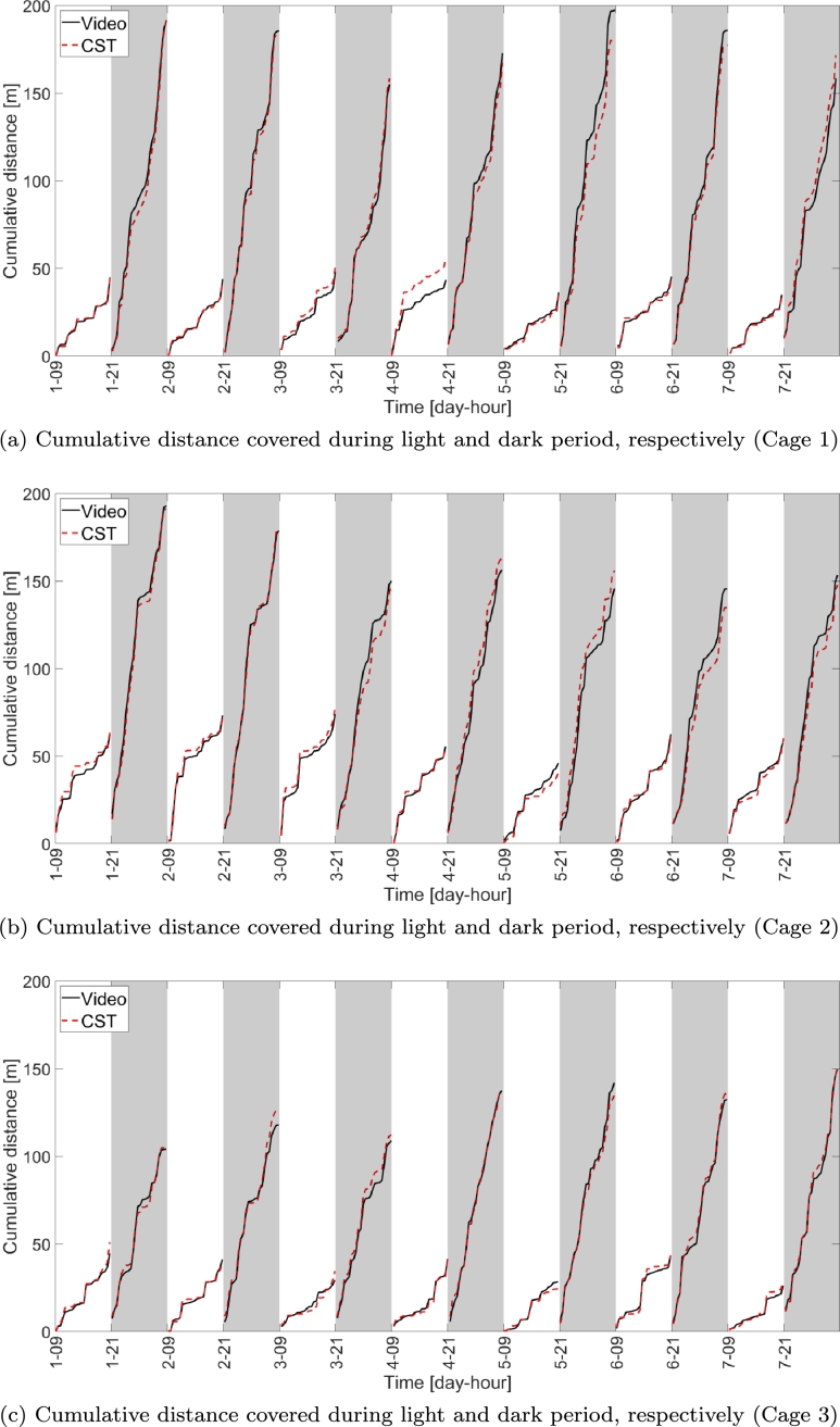
Automated home cage monitoring represents a key technology to collect animal activity information directly from the home cage. The availability of 24/7 cage data enables extensive and quantitative assessment of mouse behavior and activity over long periods of time than possible otherwise. When home cage monitoring is performed directly at the home cage rack, it is possible to leverage additional advantages, including, e.g., partial (or total) reduction of animal handling, no need for setting up external data collection system as well as not requiring dedicated labs and personnel to perform tests. In this work we introduce a home cage-home rack monitoring system that is capable of continuously detecting spontaneous animal activity occurring in the home cage directly from the home cage rack. The proposed system is based on an electrical capacitance sensing technology that enables non-intrusive and continuous home cage monitoring. We then present a few animal activity metrics that are validated via comparison against a video camera-based tracking system. The results show that the proposed home-cage monitoring system can provide animal activity metrics that are comparable to the ones derived via a conventional video tracking system, with the advantage of system scalability, limited amount of both data generated and computational capabilities required to derive metrics.

Keywords: Bioengineering; Bioinformatics; Cancer research; Genetics; Neuroscience; Physiology; Toxicology.


Figures

Figure 1
Figure 1
Capacitance sensing board installed at each cage position.
Figure 2
Figure 2
Panel a) shows the CST board with electrode numbering and the coordinates (x, y) of each electrode. Panel b) shows a side view of three electrodes together with a pictorial representation of the electromagnetic (EM) field lines (representing actual EM field lines is out of scope for this paper). Panel c) shows the effect of the presence of a mouse over an electrode that modifies the EM field lines distribution, thus causing a drop of the electrode signal (related to a change in electrical capacitance) as shown in panel d).
Figure 3
Figure 3
Screenshot of a frame captured by one of the video camera used in the test.
Figure 4
Figure 4
Distance computed via the proposed capacitance-based home cage monitoring system and video versus time (panels (a), (c) and (e)) and scatter plot comparing the two tracking systems (video on vertical axis and CST on horizontal axis) for the three cages under test (panels (b), (d) and (f)). The solid lines in the scatter plots indicate the linear fitting of the measurements while each dot corresponds to a single video block of 30 minutes. R indicates the correlation between the measurements obtained with CST and video. Gray shaded areas indicate dark periods (lights off).
Figure 5
Figure 5
Average speed computed with CST-based system and video versus time (panels (a), (c) and (e)) and scatter plot comparing the two tracking systems (video on vertical axis and CST on horizontal axis) for the three cages under test (panels (b), (d) and (f)). The solid lines in the scatter plots indicate the linear fitting of the measurements while each dot corresponds to a single video block of 30 minutes. R indicates the correlation between the measurements obtained with CST and video. Gray shaded areas indicate dark periods (lights off).
Figure 6
Figure 6
Comparison between video distance and activation density obtained with the proposed capacitance sensing technology (both normalized with respect to their maximum value in the week-long interval) in each video block versus time (panels (a), (c) and (e)) and scatter plot showing the correlation between the two metrics (video distance on vertical axis and CST activation density on horizontal axis) for the three cages under test (panels (b), (d) and (f)). The solid lines in the scatter plots indicate the linear fitting of the measurements while each dot corresponds to a single video block of 30 minutes. R indicates the correlation between the measurements obtained with CST and video.
Figure 7
Figure 7
Comparison between video activation density and CST activation density (both normalized with respect to their maximum value in the week-long interval) in each video block versus time (panels (a), (c) and (e)) and scatter plot showing the correlation between the two metrics (video activation density on vertical axis and CST activation density on horizontal axis) for the three cages under test (panels (b), (d) and (f)). The solid lines in the scatter plots indicate the linear fitting of the measurements while each dot corresponds to a single video block of 30 minutes. R indicates the correlation between the measurements obtained with CST and video.
Figure 8
Figure 8
Relative time spent in the front part of the cage measured via video and CST, respectively. Panels (a), (c) and (e) show the front part occupation versus time in the week-long interval considered. Panels (b), (d) and (f) show the scatter plot of the CST and video measurements, where each data point corresponds to a single video block of 30 minutes, while the black solid line indicates the linear regression of the measurements, while R indicates the correlation between the measurements obtained with CST and video.
Figure 9
Figure 9
Relative time spent in the rear part of the cage measured via video and CST-based system, respectively. Panels (a), (c) and (e) show the rear part occupation versus time in the week-long interval considered. Panels (b), (d) and (f) show the scatter plot of the CST-based and video measurements, where each data point corresponds to a single video block of 30 minutes, while the black solid line indicates the linear regression of the measurements, while R indicates the correlation between the measurements obtained with CST-based system and video.
Figure 10
Figure 10
Cumulative distance computed via CST-based home cage monitoring system and video versus time for the three cages under test. Covered distance is cumulated over each light and dark period, so that the last point within each period indicates the total distance covered with the corresponding period.

Similar articles

Cited by

References

    1. Baumans V. Science-based assessment of animal welfare: laboratory animals. Rev. Sci. Tech. - Int. Off. Epizoot. August 2005;24(2):503–513. http://europepmc.org/abstract/MED/16358504 - PubMed
    1. Kramer K. Evaluation and applications of radiotelemetry in small laboratory animals. Physiol. Genomics. 2003;13:197–205. - PubMed
    1. Richardson C.A. The power of automated behavioural homecage technologies in characterizing disease progression in laboratory mice: a review. Appl. Anim. Behav. Sci. 2015;163:19–27.
    1. Balzani E., Falappa M., Balci F., Tucci V. An approach to monitoring home-cage behavior in mice that facilitates data sharing. Nat. Protoc. May 2018;13:1331. - PubMed
    1. Bains R.S., Wells S., Sillito R.R., Armstrong J.D., Cater H.L., Banks G., Nolan P.M. Assessing mouse behaviour throughout the light/dark cycle using automated in-cage analysis tools. Measuring Behaviour 2016J. Neurosci. Methods. 2018;300:37–47. - PMC - PubMed