. 2019 May 7;116(9):1586-1597.
doi: 10.1016/j.bpj.2019.03.025. Epub 2019 Apr 2.

Interfacial Binding Sites for Cholesterol on G Protein-Coupled Receptors

Affiliations

Interfacial Binding Sites for Cholesterol on G Protein-Coupled Receptors

Anthony G Lee. Biophys J. .

Abstract

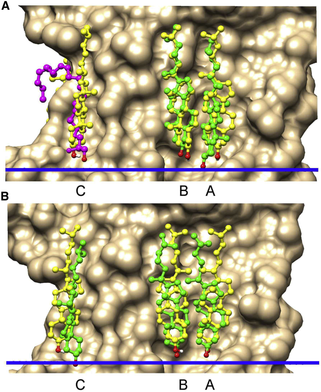
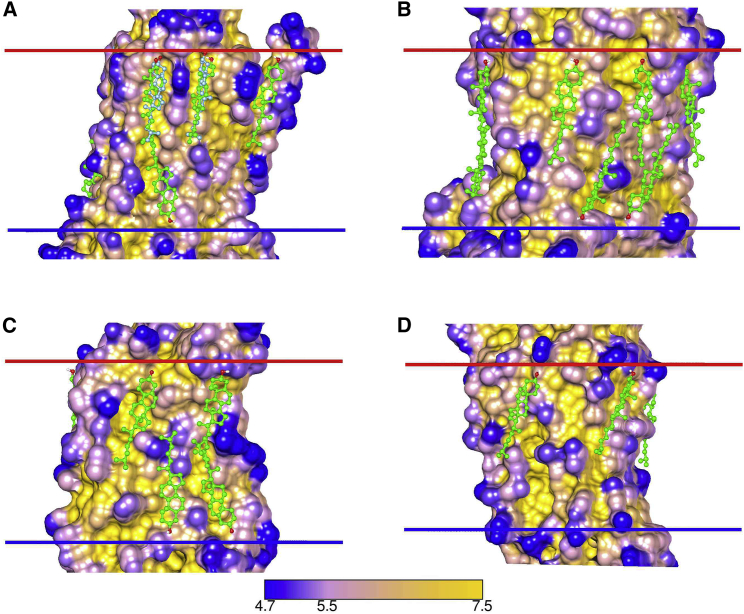
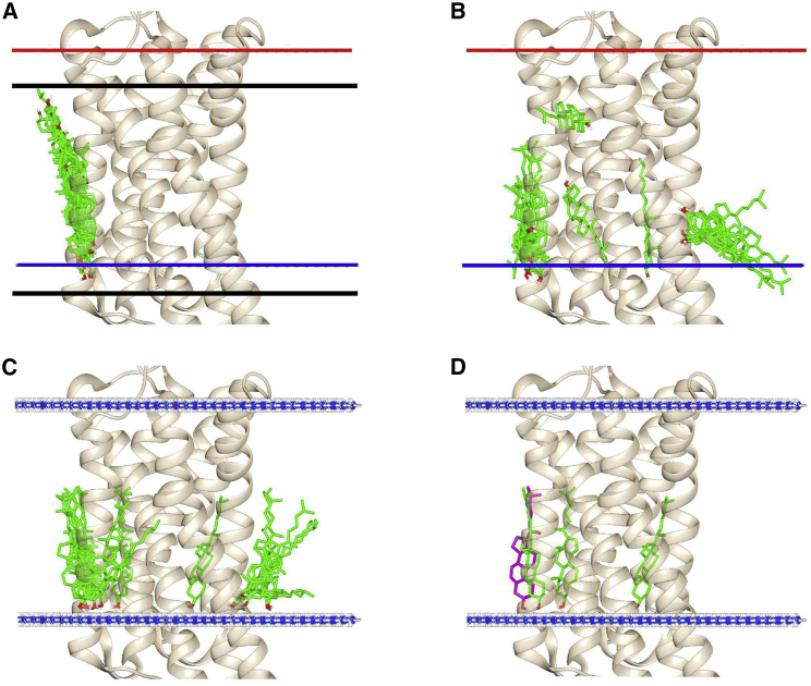
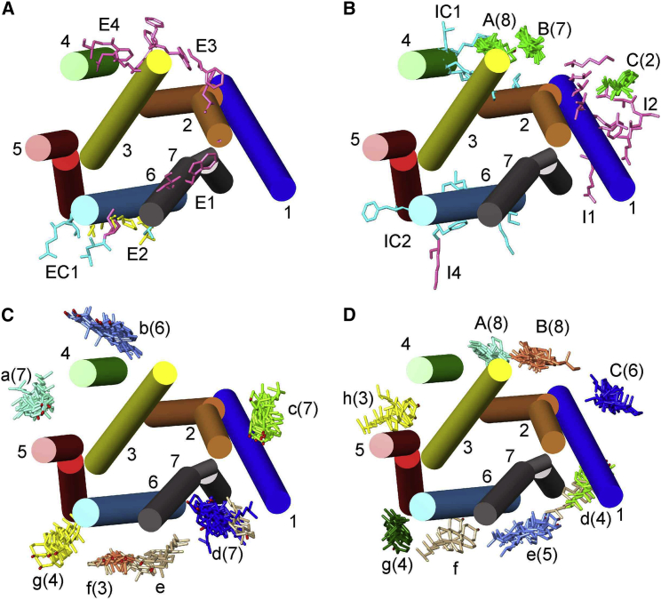
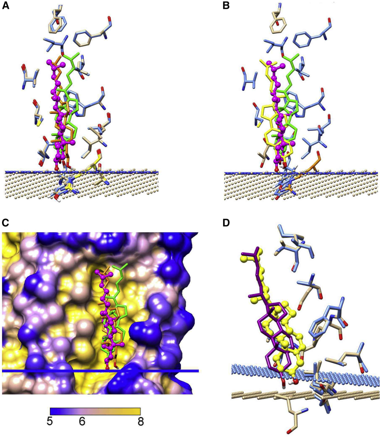
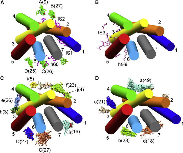
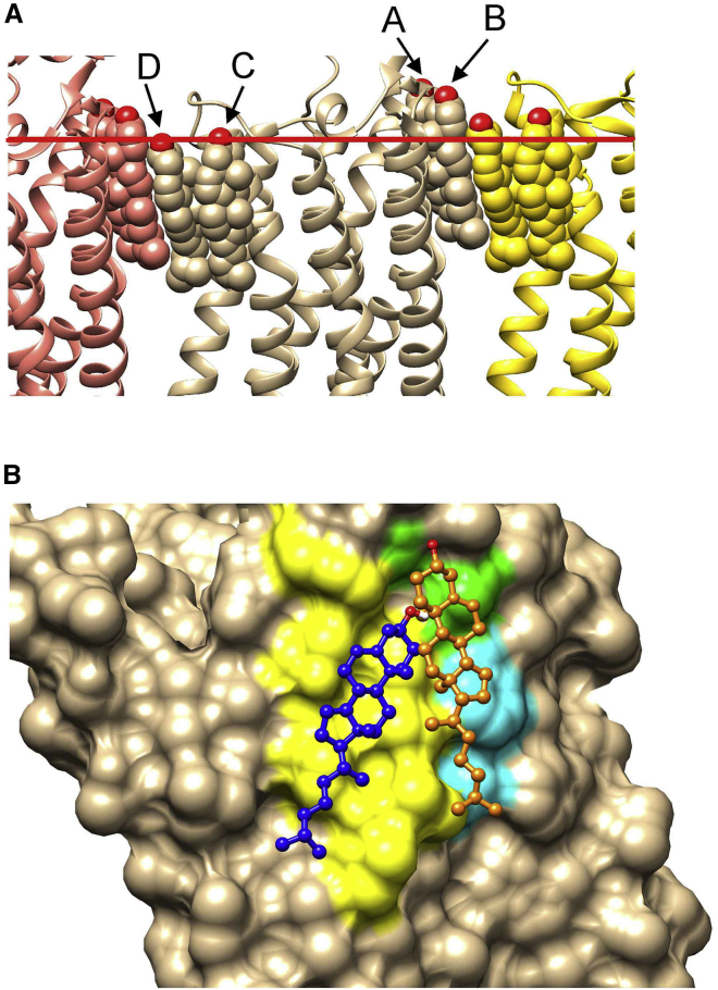
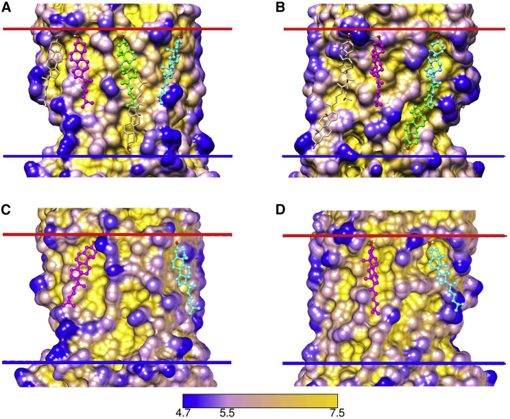
A docking procedure is described that allows the transmembrane surface of a G protein-coupled receptor (GPCR) to be swept rapidly for potential binding sites for cholesterol at the bilayer interfaces on the two sides of the membrane. The procedure matches 89% of the cholesterols resolved in published GPCR crystal structures, when cholesterols likely to be crystal packing artifacts are excluded. Docking poses are shown to form distinct clusters on the protein surface, the clusters corresponding to "greasy hollows" between protein ridges. Docking poses depend on the angle of tilt of the GPCR in the surrounding lipid bilayer. It is suggested that thermal motion could alter the optimal binding pose for a cholesterol molecule, with the range of binding poses within a cluster providing a guide to the range of thermal motions likely for a cholesterol within a binding site.


Figures

Figure 1
Figure 1
Docking and crystallographic results for β2AR. (A) and (B) show surfaces on the IC side for structures 3D4S and 5D5A, respectively. Cholesterol molecules are shown in ball and stick mode: crystallographic structures, green and docked structures, yellow. Oxygen atoms are colored red. Sites are labeled as in Table 1. For the 3D4S structure, 1-oleoyl-R-glycerol (magenta) is observed at site C in the crystal structure. The IC side of the hydrophobic slab representing the bilayer core is shown by the blue bar. To see this figure in color, go online.
Figure 2
Figure 2
Surface view of GPCRs with docked cholesterol molecules for the following: (A) Class A, A2A receptor, 5IU4; (B) Class B, calcitonin-like receptor, 6E3Y; (C) Class C, mGlu5 receptor, 4OO9; and (D) Class F, smoothened receptor, 5L7D. Surfaces are colored by distance from a bulk solvent layer calculated using the Depth program (29) with distances (Å) given by the bottom scale. Docked cholesterols are colored green, and in (A), crystallographic cholesterols are colored blue. EC and IC interfaces are shown by the red and blue bars, respectively. To see this figure in color, go online.
Figure 3
Figure 3
The docking protocol. The figure shows docking on the IC side of 3D4S. Cholesterol docking poses are shown in green (A–C) or in green and magenta (D). In (A) and (B), the locations of the EC and IC interfacial planes predicted by OPM are shown as red and blue bars, respectively; in (C) and (D), the interfacial planes have been replaced by planes of NH3 molecules (ball and stick; N, blue; H, white). In (A), the top and bottom edges of the Vina search box are shown by black lines. (A) shows the results of a single docking run with default Vina binding parameters and (B) with binding parameters appropriate for a hydrophobic environment. (C) shows the results of a single docking run with modified binding parameters and the inclusion of interfacial planes of NH3. (D) shows the three binding poses selected from the first docking run (green), together with the additional binding pose selected from the second docking run (magenta). To see this figure in color, go online.
Figure 4
Figure 4
Cluster analysis of poses for β2AR, all views being from the EC side. The eight structures included in the analysis are listed in Table 1. All structures have been aligned to 3D4S, with TM α-helices shown and numbered. (A) and (B) show crystallographic and MD results, and (C) and (D) show docking results for the EC (A and C) and IC (B and D) monolayers. In (A), residues on the EC side identified in MD simulations as being close to bound cholesterols are shown in pink (E1–E4) (13, 14) or blue (EC1) (16) and in yellow when present in both sets of MD simulations. In (B), crystallographically resolved cholesterol molecules on the IC side are shown in green, located at sites AC (Table 1); the number of cholesterols resolved at a given site is given in brackets. Residues identified in MD simulations are again shown in pink (I1, I2, I4) (13, 14) or blue (IC1, IC2) (16). (C) and (D) show clusters of poses on the EC and IC sides, respectively, colored by cluster, with single poses colored tan. The numbers in brackets give the number of poses in each cluster, and in (D), clusters corresponding to the three crystallographic sites A–C on the IC side are labeled in capitals with additional clusters in (C) and (D) in lower case. To see this figure in color, go online.
Figure 5
Figure 5
Effect of interfacial layer tilt on docking. (A) and (B) show results at site A for 3NY8 and 3NY9 after aligning the 3NY8 structure to that of 3NY9. The IC interfaces for 3NY8 and 3NY9 are shown as tan and blue spheres, respectively, together with the crystallographically resolved cholesterol for 3NY9 (ball and stick, magenta). In (A), the pose (lines) is shown for 3NY8 (orange) and 3NY9 (green). Residues close to the docked cholesterol (within 4 Å) for 3NY9 are colored blue. Residues close to the docked cholesterol for 3NY8 are colored tan when they are also close to the docked cholesterol for 3NY9 and yellow when only close to the docked cholesterol for 3NY8. (B) shows the effect on poses when the IC interface for 3NY9 is exchanged for that of 3NY8. The crystallographically resolved cholesterol for 3NY9 is shown colored magenta. The pose for 3NY9 with the 3NY9 interface (as in (A)) is colored green and that for 3NY9 with the 3NY8 interface is colored yellow. Residues close to the docked cholesterol for 3NY9 with both the 3NY9 and the 3NY8 interfaces are colored blue. Two residues close to the docked cholesterol only for 3NY9 with the 3NY9 interface are colored tan; the single residue close to the docked cholesterol only for 3NY9 with the 3NY8 interface is colored orange. (C) shows the protein surface at site A for 3NY9 colored by surface depth with cholesterol molecules colored as in (A); the blue bar shows the position of the IC interface for 3NY9. (D) shows the effect of tilt on docking at site d (Fig. 4). The pose for 3NY8 is shown in yellow (ball and stick), but no pose is observed at this site for 3NY9. However, after aligning 3NY9 to 3NY8 and replacing the 3NY9 interface with that of 3NY8, a pose is observed (lines, magenta). Residues close to the docked cholesterol for 3NY8 are shown in tan and those close to the docked cholesterol for 3NY9 with the 3NY8 interface are shown in blue. To see this figure in color, go online.
Figure 6
Figure 6
Cluster analysis of poses for A2AR, all views being from the EC side. The 27 structures included in the analysis are listed in Table S1. All structures have been aligned to 4EIY. (A) and (B) show crystallographic and MD results, and (C) and (D) show poses for the EC (A and C) and IC (B and D) monolayers. In (A), resolved cholesterols on the EC side are shown in green, located at sites AD as given in Table S1; the number of cholesterols at a given site is given in brackets. Residues identified in MD simulations as being close to bound cholesterols are shown in pink on the EC (IS1, IS2, h60) and IC (IS3, h56i) sides (17, 36). (C) and (D) show clusters of poses on the EC and IC sides, respectively, colored by cluster, with single poses colored tan. The numbers in brackets give the number of poses in each cluster, and in (C), the clusters corresponding to the crystallographic sites C and D on the EC side are labeled in capitals with additional clusters in lower case. To see this figure in color, go online.
Figure 7
Figure 7
(A) The packing interface for A2AR crystallized in the C2221 space group. An A2AR monomer in the 5MZP structure is shown (ribbons; tan), together with the two neighboring molecules that pack to give a layer structure (ribbons; orange and yellow). A2AR monomers are separated by cholesterols (spheres) packed at the protein-protein interfaces; the four cholesterols per monomer resolved in this structure are colored by the monomer to which they belong, and binding sites A–D are labeled as in Table S1. The position of the interface on the EC side as predicted by OPM is shown by the red bar. (B) The surface of an A2AR monomer is shown on the EC side of the membrane for the 4EIY structure, with the crystallographic cholesterol molecule at site B (Table S1) shown in orange (ball and stick). The pose in cluster f (Fig. 6 C) is shown in blue (ball and stick). Residues identified as being both part of cholesterol binding site IS2 predicted in MD simulations (36) and as being adjacent to the pose (blue) are shown in yellow. Residues that are only part of site IS2 are shown in light blue, and residues that are only adjacent to the pose are shown in green. To see this figure in color, go online.
Figure 8
Figure 8
Cholesterol binding to inactive (1U19) and active (2X72) forms of rhodopsin. Shown are depth-colored surface plots for inactive (A and B) and active forms (C and D) with the (A and C) and (B and D) views being related by a 180° rotation. (A) shows a pose on the EC side (green, ball and stick), part of cluster a (Fig. S2; Table S5), absent in (C); poses that are parts of cluster b (magenta, ball and stick; Fig. S2) and adjacent to TM4 (cyan, ball and stick) on the EC side are seen at equivalent positions in (A) and (C). (B) shows a pose on the IC side (green, ball and stick), part of cluster d (Fig. S2; Table S5), absent in (D); poses that are parts of clusters f (cyan, ball and stick) and i (magenta, ball and stick) on the EC side (Fig. S2) are found at equivalent positions in (B) and (D). Poses not specifically mentioned are shown colored tan. To see this figure in color, go online.

Similar articles

Cited by

References

    1. Gimpl G. Interaction of G protein coupled receptors and cholesterol. Chem. Phys. Lipids. 2016;199:61–73. - PubMed
    1. Simmonds A.C., East J.M., Lee A.G. Annular and non-annular binding sites on the (Ca2+ + Mg2+)-ATPase. Biochim. Biophys. Acta. 1982;693:398–406. - PubMed
    1. Lee A.G. How lipids affect the activities of integral membrane proteins. Biochim. Biophys. Acta. 2004;1666:62–87. - PubMed
    1. Lee A.G. Biological membranes: the importance of molecular detail. Trends Biochem. Sci. 2011;36:493–500. - PubMed
    1. Song Y., Kenworthy A.K., Sanders C.R. Cholesterol as a co-solvent and a ligand for membrane proteins. Protein Sci. 2014;23:1–22. - PMC - PubMed

MeSH terms