

A brain-plausible neuromorphic on-the-fly learning system implemented with magnetic domain wall analog memristors
- PMID: 31032402
- PMCID: PMC6486231
- DOI: 10.1126/sciadv.aau8170
A brain-plausible neuromorphic on-the-fly learning system implemented with magnetic domain wall analog memristors
Abstract
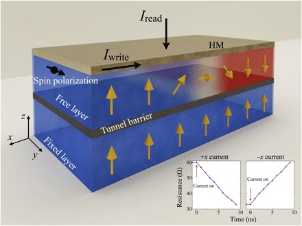
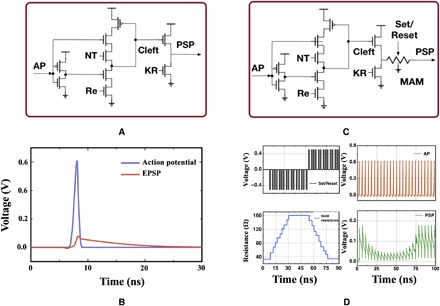
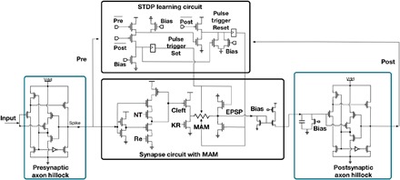
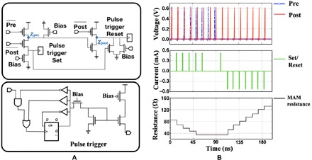
Neuromorphic computing is an approach to efficiently solve complicated learning and cognition problems like the human brain using electronics. To efficiently implement the functionality of biological neurons, nanodevices and their implementations in circuits are exploited. Here, we describe a general-purpose spiking neuromorphic system that can solve on-the-fly learning problems, based on magnetic domain wall analog memristors (MAMs) that exhibit many different states with persistence over the lifetime of the device. The research includes micromagnetic and SPICE modeling of the MAM, CMOS neuromorphic analog circuit design of synapses incorporating the MAM, and the design of hybrid CMOS/MAM spiking neuronal networks in which the MAM provides variable synapse strength with persistence. Using this neuronal neuromorphic system, simulations show that the MAM-boosted neuromorphic system can achieve persistence, can demonstrate deterministic fast on-the-fly learning with the potential for reduced circuitry complexity, and can provide increased capabilities over an all-CMOS implementation.
Figures

References
-
- Davies M., Srinivasa N., Lin T.-H., Chinya G., Cao Y., Choday S. H., Dimou G., Joshi P., Imam N., Jain S., Liao Y., Lin C.-K., Lines A., Liu R., Mathaikutty D., McCoy S., Paul A., Tse J., Venkataramanan G., Weng Y.-H., Wild A., Yang Y., Wang H., Loihi: A neuromorphic manycore processor with on-chip learning. IEEE Micro. 38, 82–99 (2018).
-
- Merolla P. A., Arthur J. V., Alvarez-Icaza R., Cassidy A. S., Sawada J., Akopyan F., Jackson B. L., Imam N., Guo C., Nakamura Y., Brezzo B., Vo I., Esser S. K., Appuswamy R., Taba B., Amir A., Flickner M. D., Risk W. P., Manohar R., Modha D. S., A million spiking-neuron integrated circuit with a scalable communication network and interface. Science 345, 668–673 (2014). - PubMed
-
- George S., Kim S., Shah S., Hasler J., Collins M., Adil F., Wunderlich R., Nease S., Ramakrishnan S., A programmable and configurable mixed-mode FPAA SoC. IEEE Trans. VLSI Syst. 24, 2253–2261 (2016).
-
- Indiveri G., Linares-Barranco B., Hamilton T. J., van Schaik A., Etienne-Cummings R., Delbruck T., Liu S.-C., Dudek P., Häfliger P., Renaud S., Schemmel J., Cauwenberghs G., Arthur J., Hynna K., Folowosele F., Saighi S., Serrano-Gotarredona T., Wijekoon J., Wang Y., Boahen K., Neuromorphic silicon neuron circuits. Front. Neurosci. 5, 73 (2011). - PMC - PubMed
-
- A. C. Parker, J. Joshi, C.-C. Hsu, N. A. D. Singh, A carbon nanotube implementation of temporal and spatial dendritic computations, in 2008 51st Midwest Symposium on Circuits and Systems (IEEE, 2008), pp. 818–821.
Publication types
MeSH terms
LinkOut - more resources
Full Text Sources
