. 2019 Apr 29;10(1):1947.
doi: 10.1038/s41467-019-09589-w.

A dynamic thermoregulatory material inspired by squid skin

Affiliations

A dynamic thermoregulatory material inspired by squid skin

Erica M Leung et al. Nat Commun. .

Abstract

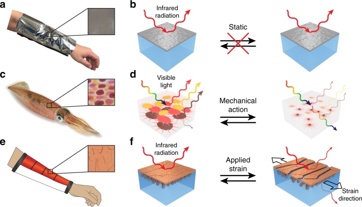
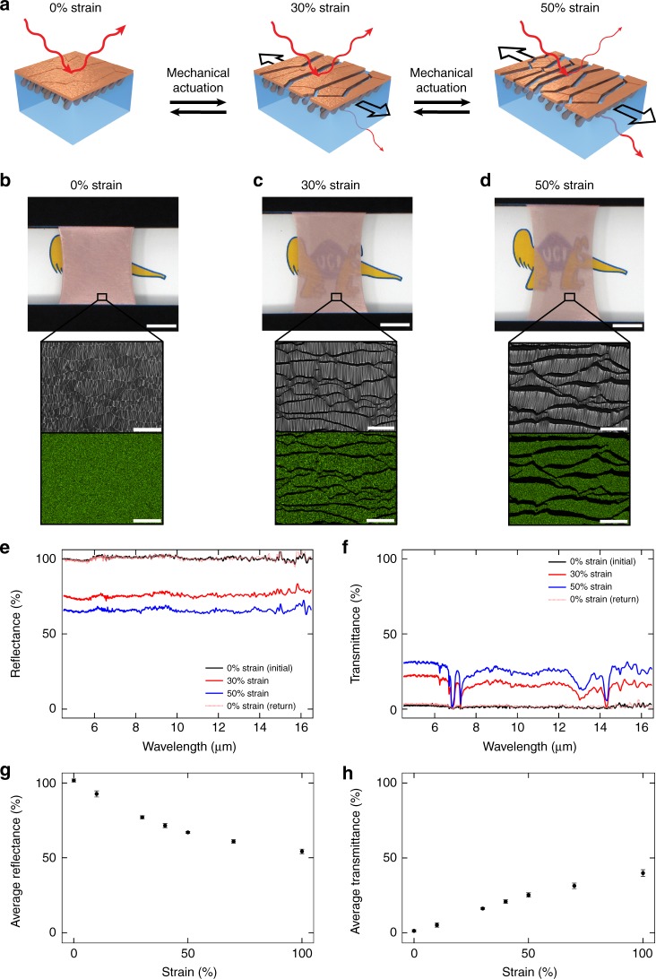
Effective thermal management is critical for the operation of many modern technologies, such as electronic circuits, smart clothing, and building environment control systems. By leveraging the static infrared-reflecting design of the space blanket and drawing inspiration from the dynamic color-changing ability of squid skin, we have developed a composite material with tunable thermoregulatory properties. Our material demonstrates an on/off switching ratio of ~25 for the transmittance, regulates a heat flux of ~36 W/m2 with an estimated mechanical power input of ~3 W/m2, and features a dynamic environmental setpoint temperature window of ~8 °C. Moreover, the composite can manage one fourth of the metabolic heat flux expected for a sedentary individual and can also modulate localized changes in a wearer's body temperature by nearly 10-fold. Due to such functionality and associated figures of merit, our material may substantially reduce building energy consumption upon widespread deployment and adoption.


Conflict of interest statement

E.M.L., S.R.J., M.F., E.M.K., K.L.N., P.P., G.T.S., and A.A.G. are listed as inventors on a provisional U.S. patent application from the University of California, Irvine, which describes the design and working principles of the reported adaptive thermoregulatory materials and systems. The remaining authors declare no competing interests.

Figures

Fig. 1
Fig. 1
Bioinspired design of the thermoregulatory composite material. a Camera image of a space blanket on a human arm. The space blanket’s outer surface is a continuous metal film (inset). b Schematics of the space blanket, which consists of a plastic (e.g., polyethylene terephthalate) sheet overlaid with a continuous metal (e.g., aluminum) layer. For this static system, an external stimulus cannot modulate the reflection and transmission of infrared radiation (left and right). c Camera image of a squid. The skin contains red, yellow, or brown chromatophore organs as illustrated by the representative inset picture. d Schematics of a layer found in squid skin, which consists of arrayed chromatophore organs embedded within a visibly-transparent dermal matrix. For this dynamic system, the mechanical action of muscle cells switches the chromatophores between expanded plate-like (left) and contracted point-like (right) states and thus modulates the reflection and transmission of specific wavelengths of visible light. e Schematic of the composite material on a human arm in a wearable (sleeve) configuration. The composite’s outer surface is a fractured multi-domain metal (e.g., copper) coating (inset). f Schematics of the composite material, which consists of an infrared-transparent polymer matrix overlaid with infrared-reflecting nanostructure-anchored metal domains. For this dynamic system, an applied strain switches the metal domain arrangement from densely (left) to sparsely (right) packed and thus modulates the reflection and transmission of infrared radiation (e.g., heat). Panel c is copyright (c) 2019 pngimg.com and made available under an Attribution-NonCommercial 4.0 International Public License. Panel c inset is copyright (c) 2012 Backyard Brains and made available under an Attribution-ShareAlike 3.0 United States Public License
Fig. 2
Fig. 2
Preparation of the thermoregulatory composite material. a Schematic of the general fabrication procedure for the composite material. The steps consist of the electron-beam deposition of a nanostructured copper film onto a support substrate (left), the spincasting of a styrene–ethylene–butylene–styrene block copolymer directly onto this film (middle), and the delamination of the resulting composite from the substrate (right). b Digital camera image of a substrate-bound nanostructured copper film (top). The scale bar is 2 cm. A representative top–down scanning electron microscopy (SEM) image demonstrates that the film consists of arrayed tilted nanoscale columns that emerge from an underlying continuous copper coating (inset). The scale bar is 200 nm. c Digital camera image of a substrate-bound composite material (top). The scale bar is 2 cm. A representative cross-sectional SEM image demonstrates that the tilted copper nanostructures are anchored within the polymer (inset). The scale bar is 500 nm. d Digital camera image of a free-standing composite material in a tape-based holder (top). The scale bar is 2 cm. A representative top–down SEM image demonstrates that the overlaid copper coating is fractured and consists of multiple abutting domains (inset). The scale bar is 20 μm
Fig. 3
Fig. 3
Mechanical actuation of changes in surface microstructure and infrared properties for the composite material. a Schematic of the mechanical actuation of the composite with strains of 0% (left), 30% (middle), and 50% (right). The surface microstructure and the reflection and transmission of infrared radiation change as a function of the applied strain. b Digital camera image of a composite under a strain of 0% above an anteater cartoon (top). The scale bar is 1 cm. A top–down scanning electron microscopy (SEM) image and copper elemental map, where the metal is colored green, for the surface of a representative composite material under a strain of 0% (inset). The scale bars are 100 μm. c Digital camera image of a composite under a strain of 30% above an anteater cartoon (top). The scale bar is 1 cm. A top–down SEM image and copper elemental map, where the metal is colored green, for the surface of a representative composite material under a strain of 30% (inset). The scale bars are 100 μm. d Digital camera image of a composite under a strain of 50% above an anteater cartoon (top). The scale bar is 1 cm. A top–down SEM image and copper elemental map, where the metal is colored green, for the surface of a representative composite material under a strain of 50% (inset). The scale bars are 100 μm. e The total infrared reflectance spectra for a representative composite material under strains of 0% (black trace), 30% (red trace), and 50% (blue trace). The reflectance observed at 0% strain is recovered even after successive actuation with higher strains (pink dotted trace). f The total infrared transmittance spectra for a representative composite material under strains of 0% (black trace), 30% (red trace), and 50% (blue trace). The transmittance observed at 0% strain is recovered even after successive actuation with higher strains (pink dotted trace). g Plot of the decrease in the average total reflectance for representative composites as a function of the applied strain. All error bars represent the standard deviation. h Plot of the increase in the average total transmittance for representative composites as a function of the applied strain. All error bars represent the standard deviation
Fig. 4
Fig. 4
Mechanical control over the setpoint temperature and thermoregulatory properties for the composite material. a Schematic of the heat flux from human skin, through the composite material, and to a variable-temperature environment without (left) and with (right) mechanical actuation. The heat flux from the skin to the surroundings increases in order to maintain the skin temperature at a constant value upon going from a cooler (left) to a warmer (right) environment. b Plot of the environmental setpoint temperatures at which an individual would remain comfortable, i.e., maintain a constant skin temperature and unchanged outgoing heat flux, while wearing either various common types of cloth (black diamonds) or the composite material at different applied strains (blue and red triangles). The calculated setpoint temperature associated with the composite can be dynamically adjusted via mechanical actuation, and the composites’ accessible setpoint temperature range is indicated by the area shaded in red and blue. c Schematic of the heat flux from a sweating-guarded hot plate, through a composite, and to a controlled environment without (left) and with (right) mechanical actuation. d Plot of the steady-state heat flux from the hot plate as a function of time for a representative composite material under strains of 0% (black dots), 30% (red dots), and 50% (blue dots)
Fig. 5
Fig. 5
Adaptive localized regulation of body temperature with a mechanically actuated composite-based sleeve. a Schematic of the infrared camera-based visualization of the outgoing heat flux and local temperature for a human subject’s sleeve-covered forearm before mechanical actuation (top) and for the same human subject’s sleeve-covered forearm after mechanical actuation (bottom). The measurements are also performed for the wearer’s bare forearm during the experiment. b Schematic of a forearm covered with a space blanket-based sleeve (top). Infrared camera image of a forearm covered with a space blanket-based sleeve and a forearm that is bare (bottom). c Schematic of a forearm covered with a composite-based sleeve under a strain of 0% (top). Infrared camera image of a forearm covered with a composite-based sleeve under a strain of 0% and a forearm that is bare (bottom). d Schematic of a forearm covered with a composite-based sleeve under a strain of 10% (top). Infrared camera image of a forearm covered with a composite-based sleeve under a strain of 10% and a forearm that is bare (bottom). e Schematic of a forearm covered with a composite-based sleeve under a strain of 30% (top). Infrared camera image of a forearm covered with a composite-based sleeve under a strain of 30% and a forearm that is bare (bottom). f Schematic of a forearm covered with a composite-based sleeve under a strain of 50% (top). Infrared camera image of a forearm covered with a composite-based sleeve under a strain of 50% and a forearm that is bare (bottom). g Plot of the increase in temperature for a forearm covered with a space blanket-based sleeve and a forearm covered with a composite-based sleeve under strains of 0% 10%, 30%, and 50%, all relative to the increase in temperature measured simultaneously for a bare forearm. All error bars represent the standard deviation

References

    1. Moore AL, Shi L. Emerging challenges and materials for thermal management of electronics. Mater. Today. 2014;17:163–174. doi: 10.1016/j.mattod.2014.04.003. - DOI
    1. Ahlers, M. F. Aircraft Thermal Management (John Wiley & Sons, New York, 2011).
    1. John M, Ford J, Harper M. Peri-operative warming devices: performance and clinical application. Anaesthesia. 2014;69:623–638. doi: 10.1111/anae.12626. - DOI - PubMed
    1. Kikuchi Y, Kanematsu Y, Sato R, Nakagaki T. Distributed cogeneration of power and heat within an energy management strategy for mitigating fossil fuel consumption. J. Ind. Ecol. 2016;20:289–303. doi: 10.1111/jiec.12374. - DOI
    1. Singh SP, Burgess G, Singh J. Performance comparison of thermal insulated packaging boxes, bags and refrigerants for single-parcel shipments. Packag. Technol. Sci. 2008;21:25–35. doi: 10.1002/pts.773. - DOI

Publication types