Review
. 2019 Apr;24(4):1-15.
doi: 10.1117/1.JBO.24.4.040902.

Photoacoustic elastography imaging: a review

Affiliations
Review

Photoacoustic elastography imaging: a review

Mayanglambam Suheshkumar Singh et al. J Biomed Opt. 2019 Apr.

Abstract

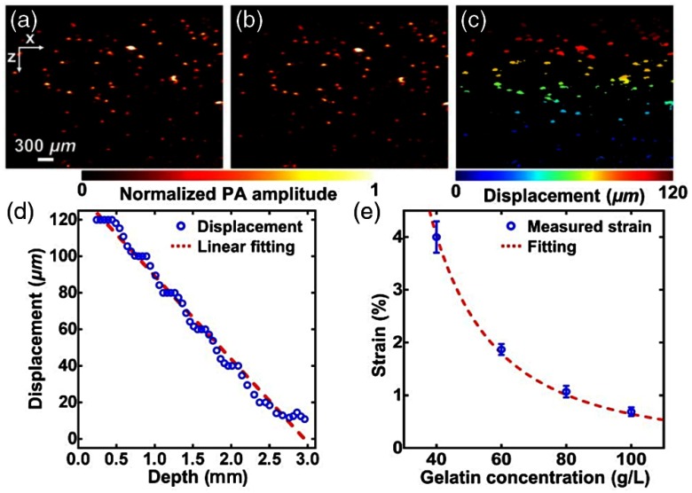
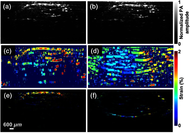
Elastography imaging is a promising tool-in both research and clinical settings-for diagnosis, staging, and therapeutic treatments of various life-threatening diseases (including brain tumors, breast cancers, prostate cancers, and Alzheimer's disease). Large variation in the physical (elastic) properties of tissue, from normal to diseased stages, enables highly sensitive characterization of pathophysiological states of the diseases. On the other hand, over the last decade or so, photoacoustic (PA) imaging-an imaging modality that combines the advantageous features of two separate imaging modalities, i.e., high spatial resolution and high contrast obtainable, respectively, from ultrasound- and optical-based modalities-has been emerging and widely studied. Recently, recovery of elastic properties of soft biological tissues-in addition to prior reported recovery of vital tissue physiological information (Hb, HbO2, SO, and total Hb), noninvasively and nondestructively, with unprecedented spatial resolution (μm) at penetration depth (cm)-has been reported. Studies demonstrating that combined recovery of mechanical tissue properties and physiological information-by a single (PA) imaging unit-pave a promising platform in clinical diagnosis and therapeutic treatments. We offer a comprehensive review of PA imaging technology, focusing on recent advances in relation to elastography. Our review draws out technological challenges pertaining to PA elastography (PAE) imaging, and viable approaches. Currently, PAE imaging is in the nurture stage of its development, where the technology is limited to qualitative study. The prevailing challenges (specifically, quantitative measurements) may be addressed in a similar way by which ultrasound elastography and optical coherence elastography were accredited for quantitative measurements.

Keywords: diagnosis; elastography; photoacoustic imaging; physiological activities; soft tissues; therapeutic treatments.


Figures

Fig. 1
Fig. 1
Classification tree of various USE imaging methods. In strain imaging, to estimate mechanical properties [Young’s modulus (E)], tissue displacement is measured by correlation of radio-frequency (RF) echo signals over a narrow prespecified search windows (boxes) in states before and after compression. While, in shear wave imaging, speed (vS) of shear wave propagation—associated with particle motion and perpendicular to direction of wave propagation—is measured and, in turn, shear modulus (G) is estimated. In B-mode imaging, particle motion parallel to direction of wave propagation is characterized to obtain speed (vL) of longitudinal wave propagation and hence, bulk modulus (B). ARFI technique is employed—in all of subgroup methods except for SE imaging and 1-D transient elastography (TE) imaging—to induce mechanical excitation of deep-seated tissue remotely. In SE imaging, tissue surface is compressed; in TE imaging, a conventional US probe is employed to induce mechanical excitation.
Fig. 2
Fig. 2
Schematic diagram of AR-PAM imaging system.
Fig. 3
Fig. 3
(a) Imaging targets (T1 to T6) of similar cross-sections (1.0  mm×0.5  mm in xz-plane) with variation in elastic coefficient were embedded in background phantom [25×20×20  mm3 (x×y×z)]. (b) Targets of different cross-sections (0.5  mm×0.5  mm to 3.0  mm×0.5  mm for T1 to T4 in xz-plane) with optical and mechanical properties similar to that of background phantom. (c) Contrast in E (with similar μa for t1) and μa (with similar E for t2) with respect to that of background sample.
Fig. 4
Fig. 4
3-D reconstructed image (a) of PA signals obtained from a sequence of 2-D PA-representative images (b) by employing Amira software. (c) Line plot showing the variation of PA signals along the line as marked in (a). (d) Variation of PA signals (as obtained from target regions) with Young’s modulus, E. Experiments were performed in sample depicted in Fig. 3(a) while a tightly focusing transducer of operating frequency 50 MHz was employed as acoustic sensor.
Fig. 5
Fig. 5
(a) Three-dimensionally reconstructed image of PA signal for raster scanning in sample (2). (b) Line plot showing variation of detected PA signals along a midline in the first frame of 3-D reconstructed image [marked line as shown in (a)]. (c) Dependence of PA signals on size of targets embedded in background.
Fig. 6
Fig. 6
For experiments performed in second sample, (a) and (d) 3-D and (b) and (e) 2-D images representative of strength of PA signals as detected by focusing US transducers [operating frequencies 50 MHz (a)–(c) and 3.5 MHz (d)–(f)]. Line-plots corresponding to the marked lines are shown in (c) and (f).
Fig. 7
Fig. 7
Variation of PA signals as obtained from target regions of third sample [Fig. 3(c)] with operating frequency of (focusing) US transducer.
Fig. 8
Fig. 8
Schematic diagram of QPAE imaging system: (a) at an elevational view and (b) at 3-D view. Lateral and elevational view of illumination of pulse laser beam in QPAE imaging system [(a) and (b)] are depicted in (c). (Figures are reproduced with permission.)
Fig. 9
Fig. 9
Measurement of strain being carried out in gelatin phantom by PAE: (a) and (b) PA images of a bilayer gelatin phantom mixed with 50 μm microspheres acquired (a) before and (b) after compression. (c) Mapping of displacement of embedded microspheres obtained from Figs. 9(a) and 9(b). (d) Variation of average displacement versus depth. Data were fitted by a linear function for each layer. (e) Measured strains of gelatin phantoms with 4%, 6%, 8%, and 10% concentration in weight. Figure shows a fit of the curve with quadratic model. (Figures are reproduced with permission.)
Fig. 10
Fig. 10
PAE images of a mouse leg in vivo (a) before and (b) after compression. (c) Strain image of mouse leg (in vivo). (d) Strain image of mouse leg obtained by USE. (e) Strain image of mouse leg obtained by PAE superimposed on structural PA image. (f) Strain image of mouse leg obtained by USE on structural ultrasound image. (Figures are reproduced with permission.)

References

    1. Greenleaf J. F., Fatemi M., Insana M., “Imaging of elastic properties of tissue—a review,” Ultrason. Med. Biol. 22(8), 959–977 (1996).USMBA310.1016/S0301-5629(96)00120-2 - DOI - PubMed
    1. Samani A., Zubovits J., Plewes D., “Elastic moduli of normal and pathological human breast tissues: an inversion-technique-based investigation of 169 samples,” Phys. Med. Biol. 52, 1565–1576 (2007).PHMBA710.1088/0031-9155/52/6/002 - DOI - PubMed
    1. Fung Y. C., Biomechanics: Mechanical Properties of Living Tissue, Springer-Verlag, New York: (1993).
    1. Krouskop T., et al. , “Elastic moduli of breast and prostate tissues under compression,” Ultrason. Imaging 20, 260–274 (1998).ULIMD410.1177/016173469802000403 - DOI - PubMed
    1. Shraiman B., “Mechanical feedback as a possible regulator of tissue growth,” Proc. Natl. Acad. Sci. U.S.A. 102, 3318–3323 (2005).PNASA610.1073/pnas.0404782102 - DOI - PMC - PubMed