A space for lattice representation and clustering
- PMID: 31041913
- PMCID: PMC6492488
- DOI: 10.1107/S2053273319002729
A space for lattice representation and clustering
Abstract
Algorithms for quantifying the differences between two lattices are used for Bravais lattice determination, database lookup for unit cells to select candidates for molecular replacement, and recently for clustering to group together images from serial crystallography. It is particularly desirable for the differences between lattices to be computed as a perturbation-stable metric, i.e. as distances that satisfy the triangle inequality, so that standard tree-based nearest-neighbor algorithms can be used, and for which small changes in the lattices involved produce small changes in the distances computed. A perturbation-stable metric space related to the reduction algorithm of Selling and to the Bravais lattice determination methods of Delone is described. Two ways of representing the space, as six-dimensional real vectors or equivalently as three-dimensional complex vectors, are presented and applications of these metrics are discussed. (Note: in his later publications, Boris Delaunay used the Russian version of his surname, Delone.).
Keywords: Delaunay; Delone; Niggli; Selling; clustering; unit-cell reduction.
open access.
Figures
 and
and  are Selling reduced. The image is the three-dimensional, all-negative octant of the three
  axes,
axes,  ,
,  and
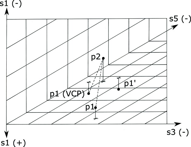
and  ; the reduction is done along the axis, and and are the two scalars that will be interchanged. The points are shown above or below the / plane, with their projections onto that plane marked with a +. To compute the minimal distance between and , begin by computing the Euclidean distance between the two. The reduction transforms into
  , but the metric changes when going from negative to positive , so the simple Euclidean distance may not be minimal. To generate
  to which the distance may be shorter, project onto the / plane, transform that projected point, and subtract from that point. The distance from to can now be used to decide whether it is shorter than the – Euclidean distance. The best distance for this case is the shorter of the distances between and as opposed to the distance between and .
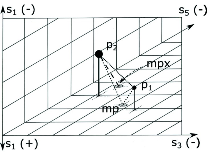 and are Selling reduced. The image is the three-dimensional, all-negative octant of the three axes, , , and ; the reduction is done along the axis, and and are the two scalars that will be interchanged. The points are shown above the / plane, with their projections onto that plane marked with a circled ‘X’. The Euclidean distance from to is shown as a dotted line. Let mp be the mirror point on the boundary going from to via the boundary. Then the shortest distance from to mp to is also shown as a dotted line. The transformed image of mp is mpx. The distance between and mp is the same as the distance between a transformed and mpx. There is a no-cost tunnel from mp to mpx. So the total alternative distance for this case is the distance between and mp plus the distance from mpx to (shown as a dashed line).
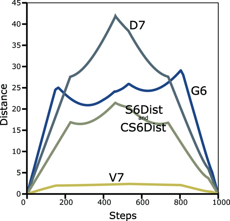
 metric (Andrews & Bernstein, 2014 ▸), the
  metric (Andrews et al., 1980 ▸), the
  metric (Andrews et al., 2019 ▸), and the two implementations in . Timing in ms: (NCDist) 4542, 676, 7, S6Dist 394, CS6Dist 14.
References
-
- Andrews, L. C. & Bernstein, H. J. (1988). Acta Cryst. A44, 1009–1018.
-
- Andrews, L. C. & Bernstein, H. J. (1995). Acta Cryst. A51, 413–416.
-
- Andrews, L. C., Bernstein, H. J. & Pelletier, G. A. (1980). Acta Cryst. A36, 248–252.
Grants and funding
- R01GM117126/National Institutes of Health, National Institute of General Medical Sciences
- P41GM103473/National Institutes of Health, National Institute of General Medical Sciences
- R21 GM129570/GM/NIGMS NIH HHS/United States
- P41GM111244/National Institutes of Health, National Institute of General Medical Sciences
- DE-AC02-98CH10886/US Department of Energy Offices of Biological and Environmental Research