. 2020 Feb;67(2):441-452.
doi: 10.1109/TBME.2019.2915165. Epub 2019 May 6.

Pose Estimation of Periacetabular Osteotomy Fragments With Intraoperative X-Ray Navigation

Pose Estimation of Periacetabular Osteotomy Fragments With Intraoperative X-Ray Navigation

Robert B Grupp et al. IEEE Trans Biomed Eng. 2020 Feb.

Abstract

Objective: State-of-the-art navigation systems for pelvic osteotomies use optical systems with external fiducials. In this paper, we propose the use of X-ray navigation for pose estimation of periacetabular fragments without fiducials.

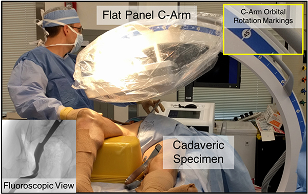
Methods: A two-dimensional/three-dimensional (2-D/3-D) registration pipeline was developed to recover fragment pose. This pipeline was tested through an extensive simulation study and six cadaveric surgeries. Using osteotomy boundaries in the fluoroscopic images, the preoperative plan was refined to more accurately match the intraoperative shape.

Results: In simulation, average fragment pose errors were 1.3 ° /1.7 mm when the planned fragment matched the intraoperative fragment, 2.2 ° /2.1 mm when the plan was not updated to match the true shape, and 1.9 ° /2.0 mm when the fragment shape was intraoperatively estimated. In cadaver experiments, the average pose errors were 2.2 ° /2.2 mm, 3.8 ° /2.5 mm, and 3.5 ° /2.2 mm when registering with the actual fragment shape, a preoperative plan, and an intraoperatively refined plan, respectively. Average errors of the lateral center edge angle were less than 2 ° for all fragment shapes in simulation and cadaver experiments.

Conclusion: The proposed pipeline is capable of accurately reporting femoral head coverage within a range clinically identified for long-term joint survivability.

Significance: Human interpretation of fragment pose is challenging and usually restricted to rotation about a single anatomical axis. The proposed pipeline provides an intraoperative estimate of rigid pose with respect to all anatomical axes, is compatible with minimally invasive incisions, and has no dependence on external fiducials.


Figures

Fig. 1.
Fig. 1.
Example of periacetabular osteotomies and a fragment reposition. This is taken from the cadaver experiments and represents the ground truth fragment pose. The manually segmented fragment shape is shown. See Fig. 3 for the corresponding intraoperative fluoroscopic images. The orientations of each anatomical axis for the anterior pelvic plane are also depicted: left/right x axis (LR), inferior/superior y axis (IS), and anterior/posterior z axis (AP).
Fig. 2.
Fig. 2.
High level workflow detailing the steps performed during the surgery and the data required for each. The registration and shape estimation steps are the primary focus of this paper.
Fig. 3.
Fig. 3.
Top Row: Intraoperative fluoroscopic images used for registering the fragment on the left side of a cadaveric specimen. Note the four BBs on the mobilized fragment and four BBs on the ilium used for ground truth computation. The left image shows an approximate AP view and the yellow circle indicates the single-landmark used for initialization of the intraoperative pipeline. Middle Row: DRRs created as part of the intensity-based registration using manual segmentation of the fragment; the final pose estimates are shown. Prior to performing any similarity comparisons, the images in the top-row will be log-corrected. Bottom Row: An example of simulated fluoroscopic data generated using the protocol of the simulation study. The image includes soft-tissue and inserted K-wires, with object poses determined by the registrations from the middle row. Despite the visual similarity with the top row, the challenge of visually determining a fragment’s pose is confirmed by an approximate 3°/3 mm pose error difference from the top row’s ground truth. See Fig. 1 for the ground truth 3D view.
Fig. 4.
Fig. 4.
An example of the 2D cut manual annotations from fluoroscopic images corresponding to the case shown in Fig. 1. Labels identifying ilium cuts are shown in (a), and labels identifying pubis cuts are shown in (b). Zoomed displays of the regions of interest in (a) and (b) are shown in (c) and (d), respectively. In (a) and (c) biege labels indicate rays that enter the pelvis surface when moving from the detector to source, while blue labels indicate rays that exit the pelvis surface. In (b) and (d), red labels indicate rays that both enter and exit the pelvis surface; the view looks approximately down the cut line.
Fig. 5.
Fig. 5.
Intraoperative setup for the PAO procedure performed on the right side of a cadaveric specimen. The current fluoroscopic view is shown in the bottom left. The enlarged region in the top right shows the markings used to control the orbital rotation of the C-Arm.
Fig. 6.
Fig. 6.
Normalized 2D histograms of fragment pose error for the simulation studies. (a) The actual fragment shape is known and matches the planned fragment shape, (b) the actual fragment shape is not known and none of the osteotomies match the planned fragment, (c) the actual fragment is partially known, with the ilium and pubis osteotomies matching the planned fragment, (d) the actual fragment is not known, but the ilium and pubis osteotomies are estimated from 2D cut lines.

References

    1. Murphy SB, Ganz R, and Müller M, “The prognosis in untreated dysplasia of the hip. A study of radiographic factors that predict the outcome,” J. Bone Joint Surg. Amer, vol. 77, no. 7, pp. 985–989, 1995. - PubMed
    1. Ganz R et al., “A new periacetabular osteotomy for the treatment of hip dysplasias technique and preliminary results,” Clin. Orthopaedics Related Res, vol. 232, pp. 26–36, 1988. - PubMed
    1. Armand M et al., “Outcome of periacetabular osteotomy: joint contact pressure calculation using standing AP radiographs, 12 patients followed for average 2 years,” Acta Orthopaedics, vol. 76, no. 3, pp. 303–313, 2005. - PMC - PubMed
    1. Armiger RS et al., “Three-dimensional mechanical evaluation of joint contact pressure in 12 periacetabular osteotomy patients with 10-year follow-up,” Acta Orthopaedics, vol. 80, no. 2, pp. 155–161, 2009. - PMC - PubMed
    1. Niknafs N et al., “Biomechanical factors in planning of periacetabular osteotomy,” Front Bioeng. Biotechnol, vol. 1, p. 20, 2013. - PMC - PubMed

Publication types