. 2019 May 9:8:e47746.
doi: 10.7554/eLife.47746.

Regulatory switch at the cytoplasmic interface controls TRPV channel gating

Affiliations

Regulatory switch at the cytoplasmic interface controls TRPV channel gating

Lejla Zubcevic et al. Elife. .

Abstract

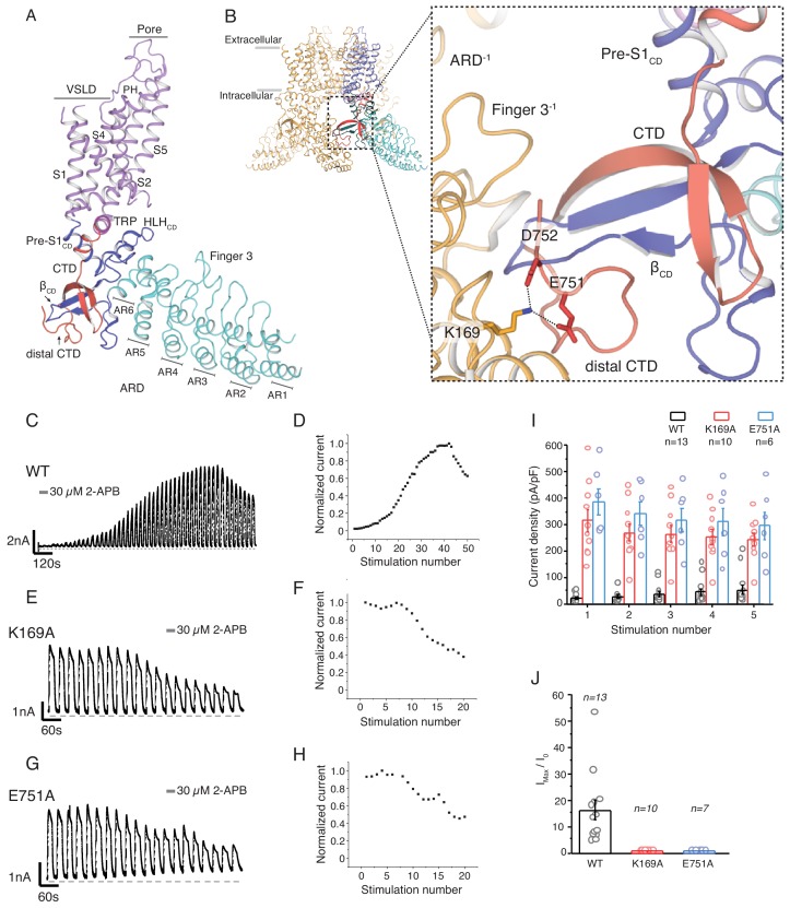
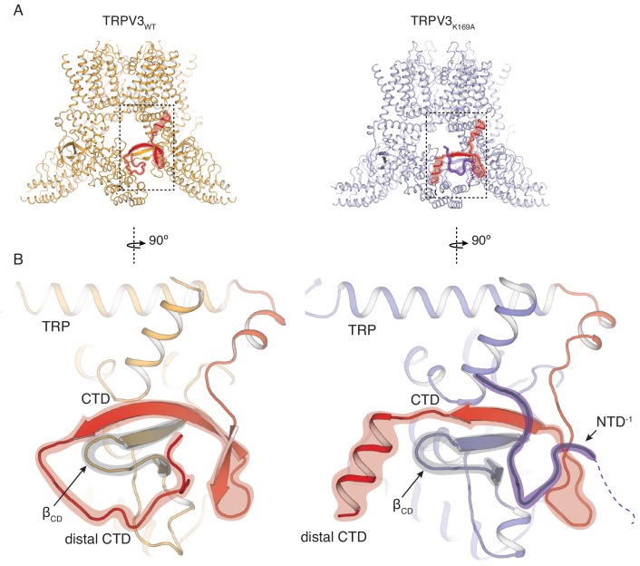
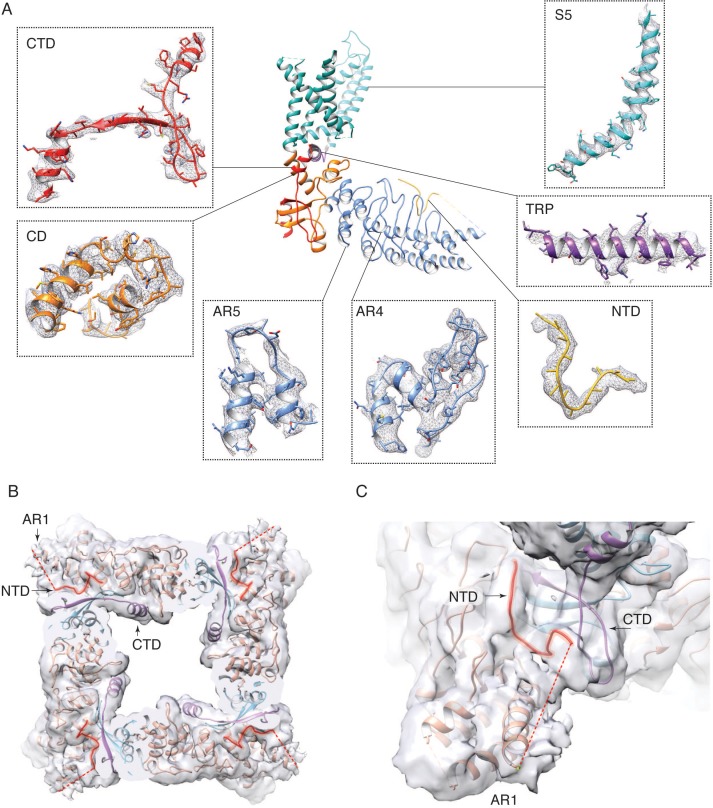
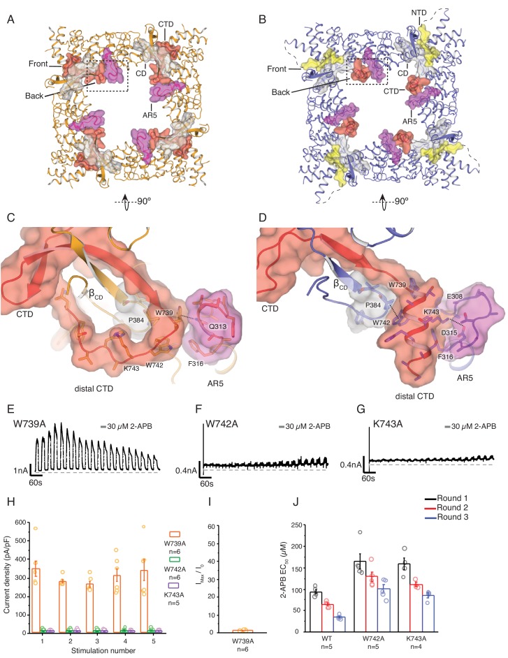
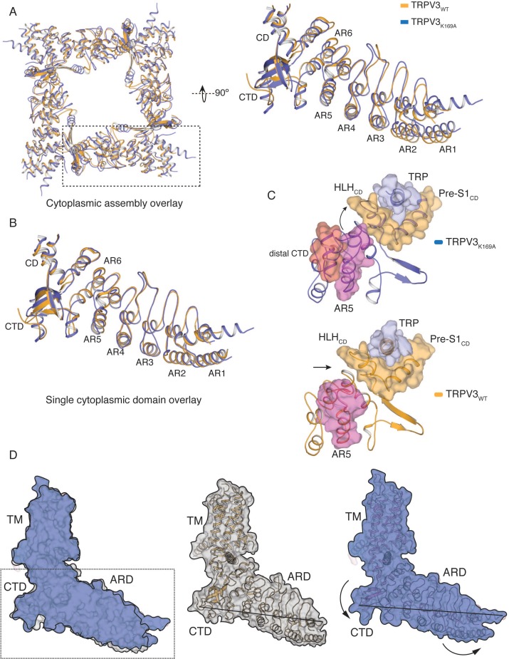
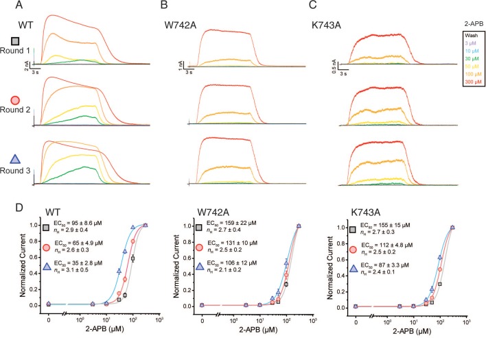
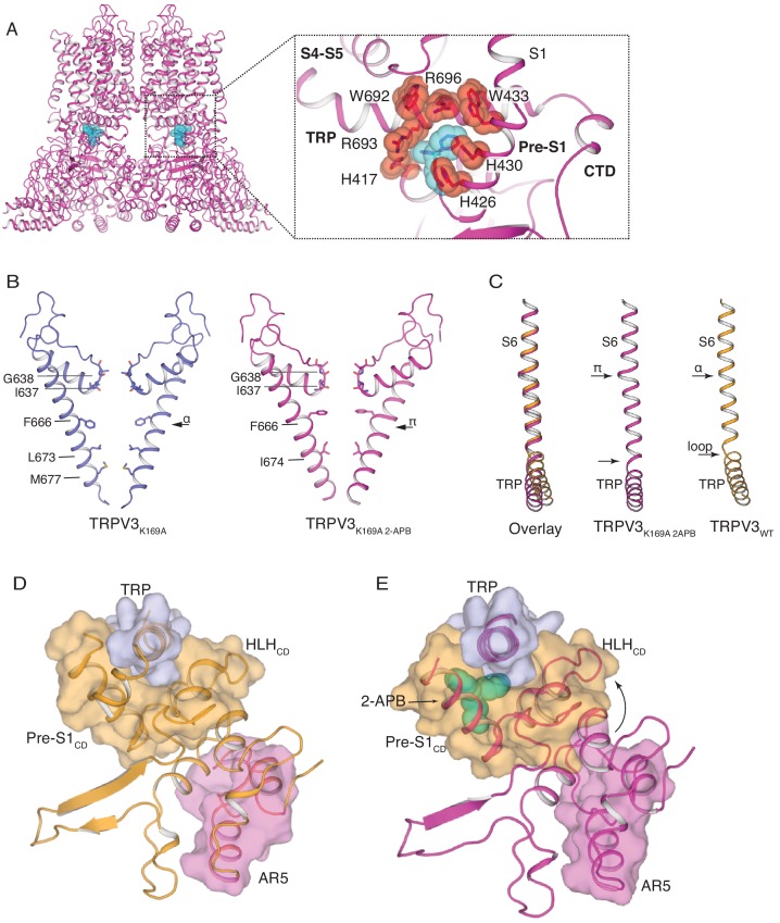
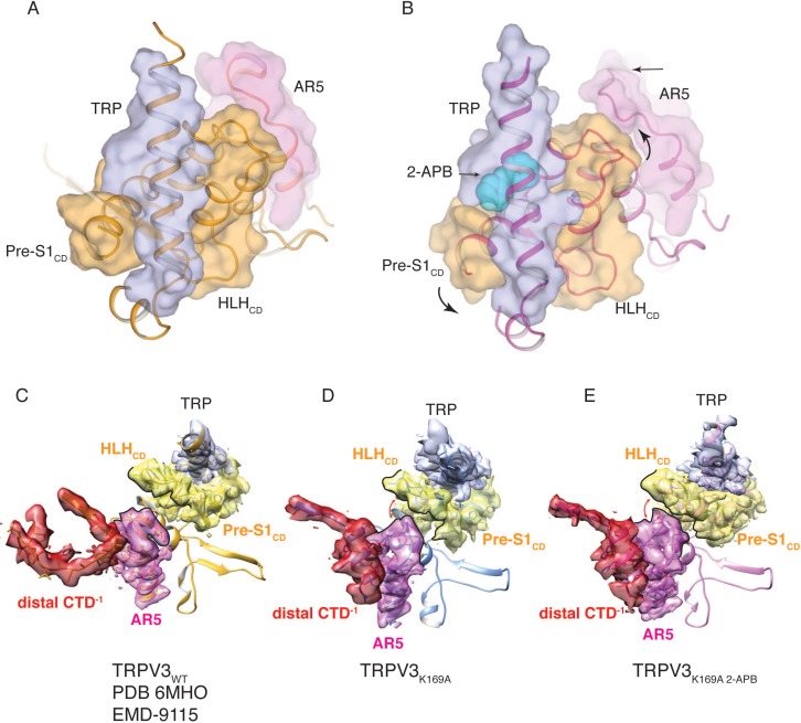
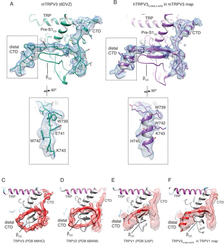
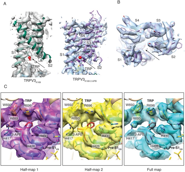
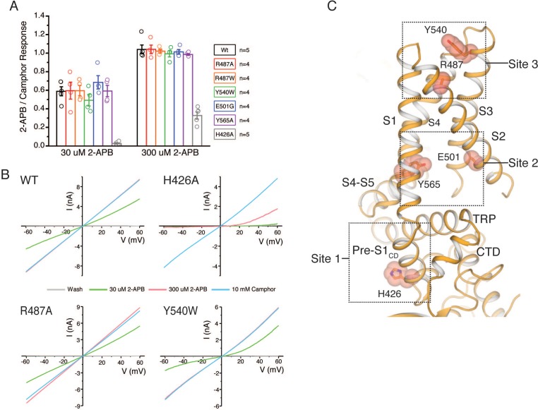
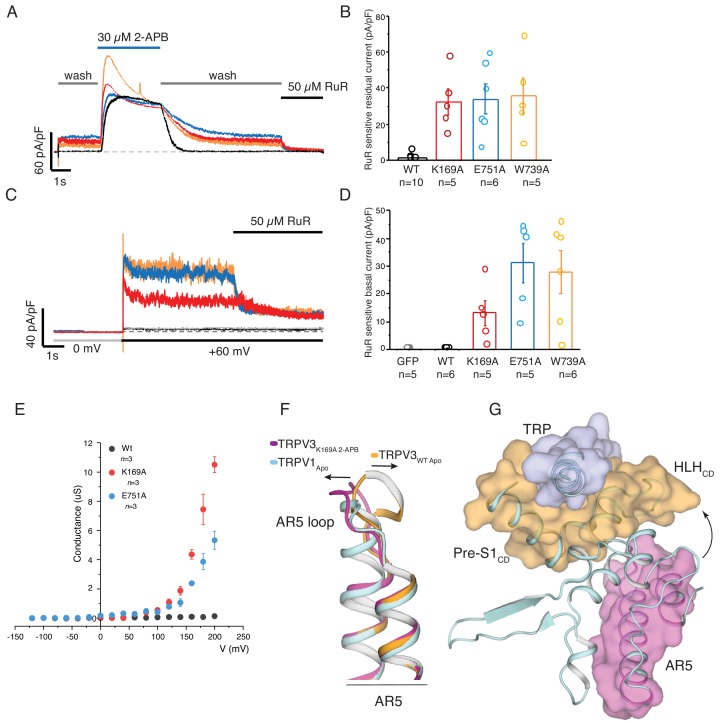
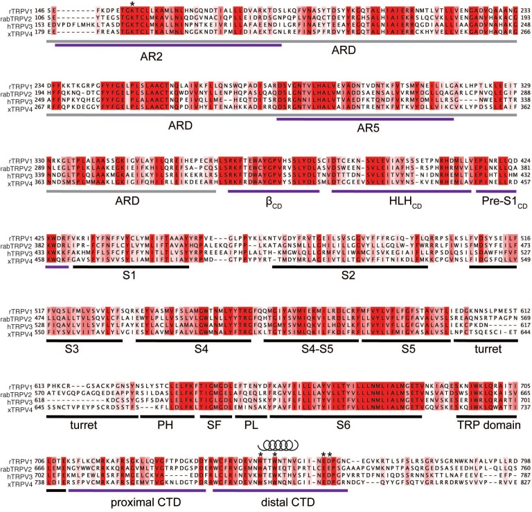
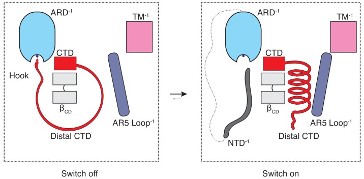
Temperature-sensitive transient receptor potential vanilloid (thermoTRPV) channels are activated by ligands and heat, and are involved in various physiological processes. ThermoTRPV channels possess a large cytoplasmic ring consisting of N-terminal ankyrin repeat domains (ARD) and C-terminal domains (CTD). The cytoplasmic inter-protomer interface is unique and consists of a CTD coiled around a β-sheet which makes contacts with the neighboring ARD. Despite much existing evidence that the cytoplasmic ring is important for thermoTRPV function, the mechanism by which this unique structure is involved in thermoTRPV gating has not been clear. Here, we present cryo-EM and electrophysiological studies which demonstrate that TRPV3 gating involves large rearrangements at the cytoplasmic inter-protomer interface and that this motion triggers coupling between cytoplasmic and transmembrane domains, priming the channel for opening. Furthermore, our studies unveil the role of this interface in the distinct biophysical and physiological properties of individual thermoTRPV subtypes.

Keywords: TRP channel; cryo-electronmicroscopy; electrophysiology; human; ion channel; ligand dependent gating; molecular biophysics; sensitization; structural biology.


Conflict of interest statement

LZ, WB, AH, MB, SL No competing interests declared

Figures

Figure 1.
Figure 1.. The role of the cytoplasmic inter-protomer interface in hTRPV3 gating.
(A) Architecture of the hTRPV3 protomer. Ankyrin repeat domain (ARD) is colored in cyan, the coupling domain (CD) and its individual elements (HLHCD, βCD, Pre-S1CD) are colored in blue, transmembrane helices S1-S6 are colored in violet, the TRP domain is shown in magenta and the C-terminal domain (CTD) is colored in red. (B) A close-up view of the inter-protomer interface in hTRPV3. Residue K169 from the ARD and residues E751 and D752 from the CTD are shown in stick representation. Representative whole-cell current traces recorded at +60 mV from WT (C–D), K169A (E–F), and E751A (G–H) evoked by repeating applications 30 μM 2-APB for 15 s followed by 15 s of washout and corresponding time-course of use-dependent changes in the relative current amplitude. (I) Average current density from the first five 2-APB stimulations (WT: n = 13 biologically independent experiments; K169A: n = 10 biologically independent experiments; E751A: n = 6 biologically independent experiments). (J) Initial sensitization was characterized by the ratio of the response to 2-APB during the first (I0) and maximum current (Imax) response (Imax/I0) calculated as the mean from each biologically independent experiment. (WT: n = 13 biologically independent experiments; K169A: n = 10 biologically independent experiments; E751A: n = 7 biologically independent experiments).
Figure 1—figure supplement 1.
Figure 1—figure supplement 1.. State model and gating schemes of TRPV3 channels.
Simple state model of TRPV3 gating proposed by Liu et al. (2011). The transition rate from C1 → C0 (scheme 1) and O→C0 (scheme 2) is slow enough that this transition is irreversible. Both k0 and k1 transition rates are stimulant [s] dependent (heat or chemical agonist). Following removal of the stimulus, channels return to a closed intermediate state (C1) in scheme 1 or a new resting state (C1) in scheme 2. During consecutive stimulations, the occupancy of C1 increases, leading to greater sensitivity to the stimulus in a use-dependent manner.
Figure 2.
Figure 2.. Rearrangements of the cytoplasmic domains in the TRPV3K169A structure.
(A) The cytoplasmic inter-protomer interface in TRPV3WT (left panel) and TRPV3K169A (right panel). The CTD and the putative N-terminal region are highlighted in red and purple, respectively. (B) Close-up view of the rearrangements in the cytoplasmic domains. In the TRPV3WT, the distal CTD (highlighted in red) coils around the βCD (highlighted in grey) (left panel). In the TRPV3K169A structure, the distal CTD undergoes a coil-to-helix transition (highlighted in red). An additional polypeptide density (highlighted in purple) is observed near the front of the βCD (highlighted in grey) and the proximal CTD, in the vicinity of the space occupied by the distal CTD coil in TRPV3WT and was assigned as a putative N-terminal domain from the neighboring protomer (NTD−1).
Figure 2—figure supplement 1.
Figure 2—figure supplement 1.. Cryo-EM data collection and processing, TRPV3K169A.
(A) A representative micrograph from the TRPV3K169A data collection. (B) 3D reconstruction workflow. (C) Euler distribution plot. Red regions show the best represented views. (D) Local resolution estimate, calculated in Relion. (E) FSC curves calculated between the half maps (blue), atomic model and the full map (red) and between the model and each half-map (orange and green).
Figure 2—figure supplement 2.
Figure 2—figure supplement 2.. Electron density in the TRPV3K169A cryo-EM map.
(A) Representative electron densities in the TRPV3K169A cryo-EM map. Densities are contoured at level 0.015 and radius 2. (B–C) Connectivity between the ARD and the putative N-terminal region. The unsharpened TRPV3K169A map is contoured at level 0.006.
Figure 3.
Figure 3.. State-dependent changes at the cytoplasmic inter-protomer interface.
(A–B) Top view of the cytoplasmic inter-protomer interactions in TRPV3WT (A) and TRPV3K169A (B). In TRPV3WT the CTD (red) coils around the βCD (grey). The distal CTD interacts with the ARD at the front of the interface and with the loop of ankyrin repeat 5 (AR5, magenta) at the back. In TRPV3K169A, the interface is changed due to the coil-to-helix transition in the distal CTD, which no longer participates in the interactions at the front of the interface and forms tighter interactions with AR5. The front of the interface is now occupied by the putative NTD (yellow). (C) A close-up view from the cytoplasmic cavity of the interactions between the distal CTD (red surface representation) and AR5 (magenta surface representation) in TRPV3WT. Residue W739 forms a cation-π interaction with the amino group of Q313 (dashed line). (D) The coil-to-helix transition changes the conformation of the AR5 loop. In TRPV3K169A, the W739-Q313 interaction is broken. Residues K742 and W743, which in TRPV3WT are not within interaction distances with the rest of the protein, form interactions with the backbone of E308 in AR5 and P384 in βCD, respectively (dashed lines). Representative whole-cell current traces recorded at +60 mV from W739A (E), W742A (F), and K743A (G) evoked by repeating applications 30 μM 2-APB for 15 s followed by 15 s of washout. (H) Average current density for the first five 2-APB stimulations (W739A: n = 6 biologically independent experiments; W742A: n = 6 biologically independent experiments; K743A: n = 5 biologically independent experiments). (I) Ratio of first (I0) and maximum current (Imax) 2-APB stimulation (Imax/I0) as in (G), calculated as the mean from each biologically independent experiment (W739A: n = 6 biologically independent experiments). (J) Mean 2-APB EC50 from three consecutive dose-response rounds fit with the Hill equation (WT: n = 5 biologically independent experiments; W742A: n = 5 biologically independent experiments; K743A: n = 4 biologically independent experiments). See Figure 3—figure supplement 2 for representative current traces and dose–response relationship fit with the Hill equation.
Figure 3—figure supplement 1.
Figure 3—figure supplement 1.. Conformational changes in the cytoplasmic domains in TRPV3K169A.
(A) Overlay of the tetrameric cytoplasmic assemblies from TRPV3WT (orange) and TRPV3K169A (blue). Close-up view single ARD shows that the tetrameric assemblies cannot be superposed through a rigid body rotation. (B) Individual ARDs, not attached to the tetrameric assembly, from TRPV3WT (orange) and TRPV3K169A (blue) can be superposed. (C) In the TRPV3WT (orange, bottom) structure there is no coupling between the AR5 (magenta) and the HLHCD (orange). However, in TRPV3K169A (blue, top) upon coil-to-helix transition in the distal CTD (red), the CTD-AR5 (magenta) interaction forces a change in conformation in the loop of AR5, bringing it within interaction distance of HLHCD (orange). (D) Surface representation of the overlay between single protomers of TRPV3WT (orange cartoon, gray surface) and TRPV3K169A (blue cartoon, blue surface). The overlay shows that the TM domains overlay well, while the cytoplasmic domains exhibit substantial differences. The cytoplasmic assembly of TRPV3K169A (right panel) swivels, so that the N-terminal part is lifted up toward the membrane while the C-terminal part is lowered into the cytosol. The line drawn between the tip of the βCD and residue A110 in AR1 indicates the relative movement within the cytoplasmic assembly.
Figure 3—figure supplement 2.
Figure 3—figure supplement 2.. The TRPV3 W742A and K743A CTD mutants alter hysteresis.
Three consecutive rounds of 2-APB dose-responses (0 (black) 3(purple), 10 (blue), 30 (green), 50 (yellow), 100 (orange), 300 (red) μM) was applied for 15 s followed 15 s of wash for WT (A) W742A (B) and K743A (C) at +60 mV. (D) Averaged dose-response of WT, W742A, and K743A from the first (square), second (circle), and third (triangle) consecutive dose-response round. Inset is EC50 and hill coefficient (nH) fitted to the average normalized current at each 2-APB concentration per round (WT: n = 5 biologically independent experiments; W742A: n = 5 biologically independent experiments; K743AA: n = 4 biologically independent experiments).
Figure 4.
Figure 4.. The structure of TRPV3K169A 2-APB exhibits changes in both transmembrane and cytoplasmic domains.
(A) One 2-APB molecule is bound to each protomer of the TRPV3K169A 2-APB channel (magenta). 2-APB is found between the HLHCD, Pre-S1CD and TRP domains in a binding site defined by residues H417 in the HLHCD, H426, H430, W433 in the Pre-S1CD and W692, R693 and R696 in the TRP domain. All residues are shown in stick and red sphere representation. 2-APB is shown in stick and cyan sphere representation. (B) The S6 helix of TRPV3K169A (blue) undergoes an α-to-π transition in the presence of 2-APB (magenta). (C) The α-to-π transition tightens the connection between S6 and the TRP domain. In the TRPV3WT structure (orange), the TRP domain and the S6 are connected via a loop, but in the TRPV3K169A 2-APB channel (magenta) the TRP domain and S6 form a continuous helical structure. In addition, the TRP domain exhibits a swivel in the TRPV3K169A 2-APB structure. (D–E) The coil-to-helix transition in TRPV3K169A 2-APB increases coupling between the cytoplasmic domains and the TRP domain. In the TRPV3WT structure (orange) (D), the loop of AR5 (magenta surface) does not interact with the HLHCD (orange surface). However, in TRPV3K169A 2-APB (magenta) (E) the coil-to-helix transition in the distal CTD induces a conformational change in the loop of AR5 (magenta surface), coupling it to the HLHCD (orange surface) and the TRP domain (light blue surface). 2-APB (cyan stick and surface representation) contributes to increased interactions between the TRP domain and Pre-S1CD.
Figure 4—figure supplement 1.
Figure 4—figure supplement 1.. Cryo-EM data collection and processing, TRPV3K169A 2-APB.
(A) A representative micrograph from TRPV3K169A 2-APB data collection. (B) 3D reconstruction workflow. (C) Euler distribution plot. Red regions show the most represented views. (D) Local resolution estimate, calculated in Relion. (E) FSC curves calculated between the half maps (blue), atomic model and the full map (red) and between the model and each half-map (orange and green).
Figure 4—figure supplement 2.
Figure 4—figure supplement 2.. Electron density in the TRPV3K169A 2-APB cryo-EM map.
Representative electron densities in the TRPV3K169A 2-APB cryo-EM map. Densities are contoured at level 0.03 and radius 2. The inset in the S6 panel shows a close-up of the density around the π-helical turn contoured at level 0.02 and radius 2. The black solid lines represent the H-bonds in the α-helix, which are broken in the π-helical turn.
Figure 4—figure supplement 3.
Figure 4—figure supplement 3.. Comparison of the pore conformations of hTRPV3WT, hTRPV3K169A 2-APB and mTRPV3Open.
Bottom-up view of the hTRPV3WT (PDB ID 6MHO, orange), hTRPV3K169A 2-APB (magenta) and mTRPV3Open (PDB ID 6DVZ, green) pores. The conformation of hTRPV3K169A 2-APB resembles that of the mTRPV3Open (Overlay).
Figure 4—figure supplement 4.
Figure 4—figure supplement 4.. Coupling between the cytoplasmic and transmembrane domains.
(A) Top view of the coupling between the TRP domain (light blue), the CD (orange, Pre-S1CD and HLHCD) and the AR5 (magenta) in TRPV3WT. (B) In the TRPV3K169A 2-APB structure, the coil-to-helix transition in the CTD forces the loop AR5 to change conformation (magenta) and interact with HLHCD (orange). This induces a swivel in the CD (orange) and the TRP domain (light blue). 2-APB (cyan spheres) further increases the coupling between the CD and the TRP domain. (C–E) Electron density around the CTD, AR5, CD and TRP domain in TRPV3WT (C), TRPV3K169A (D) and TRPV3K169A 2APB (E) viewed from inside of the cytoplasmic vestibule. The density is contoured at level 0.02 in TRPV3WT, 0.01 in TRPV3K169A and 0.02 in TRPV3K169A 2-APB.
Figure 4—figure supplement 5.
Figure 4—figure supplement 5.. The CTD in thermoTRPV structures.
(A) The cryo-EM map (EMD-8921) and atomic structure of the open mTRPV3 (PDB 6DVZ). Close-up view shows the fit of the CTD region into the electron density. (B) hTRPV3K169A 2-APB fit into the cryo-EM map of the open mTRPV3 (EMD-8921). Close-up view shows that the electron density can more feasibly be built as a helix. (C) The cryo-EM map (EMD-9115) and atomic structure of the hTRPV3 apo, closed state (PDB ID 6MHO). (D) The X-ray crystallographic electron density and atomic structure of the apo closed rabbit TRPV2 (PDB ID 6BWM). (E) The cryo-EM map (EMD-5778) and atomic structure of the apo, closed rTRPV1 (PDB ID 3J5P). (F) hTRPV3K169A 2-APB fit into the cryo-EM map of the open apo, closed rTRPV1 (EMD-5778).
Figure 4—figure supplement 6.
Figure 4—figure supplement 6.. APB binding in TRPV3K169A 2APB.
(A) Non-assigned densities (red) in the VSLD cavity of TRPV3K169A (green, left) and TRPV3K169A 2-APB (purple, right). Electron densities are contoured at levels 0.015 and 0.03, respectively. (B) No electron density is present at the proposed third 2-APB binding site at the extracellular side of the VSLD (arrow). Electron density is contoured at level 0.03. (C) Binding of 2-APB (red stick representation) between the TRP domain (yellow) and Pre-S1CD (green) in TRPV3K169A 2-APB half-map 1 (magenta, contoured at 0.0175), half-map 2 (yellow, contoured at 0.0175) and full map (blue, contoured at 0.03).
Figure 4—figure supplement 7.
Figure 4—figure supplement 7.. APB and camphor response of proposed 2-APB binding site mutants.
(A) Graphical representation of the current response ratio of sub- (30 μM) and saturating 2-APB (300 μM) to camphor (10 mM) calculated as the mean from each biologically independent experiment. (WT: n = 5 biologically independent experiments; R487A: n = 4 biologically independent experiments; R487W: n = 4 biologically independent experiments; Y540W: n = 4 biologically independent experiments; E501G: n = 4 biologically independent experiments; Y540A: n = 4 biologically independent experiments; Y565A: n = 4 biologically independent experiments; H426A: n = 5 biologically independent experiments;). (B) Representative voltage ramp (−60 to +60 mV, 400 ms) traces to wash (gray), 30 (green) and 300 (red) μM 2-APB, and 10 mM camphor (blue). Only H426A possessed a lower 2-APB to camphor ratio compared to WT channels. (C) Protomer of mouse TRPV3 Y654A mutant bound to 2-APB (PDB ID 6DVZ) with three proposed binding sites highlighted (dotted boxes) (Singh et al., 2018). Mutated residues are shown in stick and sphere representation.
Figure 5.
Figure 5.. Parallels between TRPV3K169A and wild-type TRPV1.
(A) Representative whole-cell recording at +60 mV of WT (black), K169A (red), E751A (blue), W739A (orange) immediately following 2-APB sensitization protocol, with perfusion protocol of 5 s wash, followed by 15 s 30 μM 2-APB, prolonged 30 s wash and the residual current was blocked by 5 s application of 50 μM ruthenium red (RuR). The scale bars units are in current density (pA/pF). (B) Graphical representation of RuR sensitive residual current at the end of the recording in (A) (WT: n = 10 biologically independent experiments; K169A: n = 5 biologically independent experiments; E751A: n = 6 biologically independent experiments, W739A: n = 5 biologically independent experiments). (C) Basal current activity before application of ligand was determined by the blocking the current following a voltage step from 0 to +60 mV with 50 μM RuR. (D) Graphical representation of the mean blocked current density from the protocol in (C) (GFP control: n = 5 biologically independent experiments; WT: n = 6 biologically independent experiments; K169A: n = 5 biologically independent experiments; E751A: n = 5 biologically independent experiments, W739A: n = 6 biologically independent experiments). (E) Conductance voltage relation of WT, K169A, and E751A in the absence of ligand determined from peak tail current elicited from a −160 mV post step pulse following a voltage step between −120 to +200 mV (Δ 20 mV). The conductance of both mutants fail to saturate at +200 mV while WT channels are nonconductive at the tested voltages (WT: n = 3 biologically independent experiments; K169A: n = 3 biologically independent experiments; E751A: n = 3 biologically independent experiments). (F) Alignment of AR5 from TRPV3WT (orange), TRPV3K169A 2APB (magenta) and TRPV1 (light cyan). The AR5 loop of TRPV1 assumes a conformation similar to that of TRPV3K169A 2APB. (G) The AR5 loop and the HLHCD are within interaction distance in TRPV1.
Figure 5—figure supplement 1.
Figure 5—figure supplement 1.. Sequence alignment of rat TRPV1 (rTRPV), rabbit TRPV2 (rabTRPV2), human TRPV3 (hTRPV3) and xenopus TRPV4 (xTRPV4).
The alignment is colored by conservation and regions of interest are marked with purple lines. residues of interest are indicated with *. The distal CTD has a high helical propensity as calculated by PsiPred. Indicated by a helix cartoon. Abbreviations: ARD, ankyrin repeat domain; AR2, ankyrin repeat 2; AR5, ankyrin repeat 5; βCD, β-sheet of the coupling domain (CD); HLH CD, helix-loop-helix of the CD; Pre-S1 CD, Pre-S1 of the CD; PH, pore helix; SF, selectivity filter; PL, pore loop.
Figure 6.
Figure 6.. The CTD-mediated ‘switch’ gating mechanism.
In the naive closed state (C0), the distal CTD is stretched around the βCD via a salt bridge ‘hook’ interaction with the ARD and the switch is ‘off’. When the CTD is ‘unhooked’ from the ARD, it undergoes a coil-to-helix transition (the switch turns ‘on’) which leads to a conformational change in the loop of AR5 and consequently to increased coupling between the cytoplasmic and transmembrane domains, which is prerequisite for channel opening (C1).

References

    1. Adams PD, Afonine PV, Bunkóczi G, Chen VB, Davis IW, Echols N, Headd JJ, Hung LW, Kapral GJ, Grosse-Kunstleve RW, McCoy AJ, Moriarty NW, Oeffner R, Read RJ, Richardson DC, Richardson JS, Terwilliger TC, Zwart PH. PHENIX: a comprehensive Python-based system for macromolecular structure solution. Acta Crystallographica Section D Biological Crystallography. 2010;66:213–221. doi: 10.1107/S0907444909052925. - DOI - PMC - PubMed
    1. Bang S, Yoo S, Yang TJ, Cho H, Hwang SW. Farnesyl pyrophosphate is a novel pain-producing molecule via specific activation of TRPV3. Journal of Biological Chemistry. 2010;285:19362–19371. doi: 10.1074/jbc.M109.087742. - DOI - PMC - PubMed
    1. Brauchi S, Orta G, Salazar M, Rosenmann E, Latorre R. A hot-sensing cold receptor: C-terminal domain determines thermosensation in transient receptor potential channels. Journal of Neuroscience. 2006;26:4835–4840. doi: 10.1523/JNEUROSCI.5080-05.2006. - DOI - PMC - PubMed
    1. Cao E, Liao M, Cheng Y, Julius D. TRPV1 structures in distinct conformations reveal activation mechanisms. Nature. 2013;504:113–118. doi: 10.1038/nature12823. - DOI - PMC - PubMed
    1. Caterina MJ, Schumacher MA, Tominaga M, Rosen TA, Levine JD, Julius D. The capsaicin receptor: a heat-activated ion channel in the pain pathway. Nature. 1997;389:816–824. doi: 10.1038/39807. - DOI - PubMed

Publication types

Associated data