. 2019 May 28;13(5):5439-5450.
doi: 10.1021/acsnano.9b00220. Epub 2019 May 16.

Shape and Size Control of Artificial Cells for Bottom-Up Biology

Affiliations

Shape and Size Control of Artificial Cells for Bottom-Up Biology

Federico Fanalista et al. ACS Nano. .

Abstract

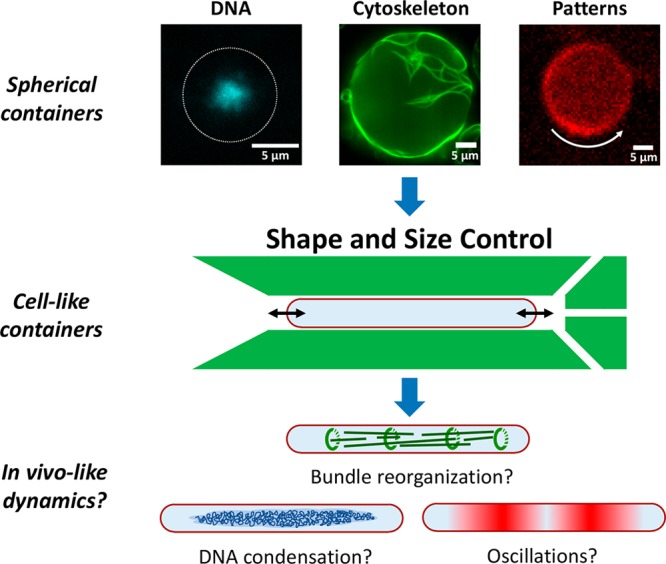
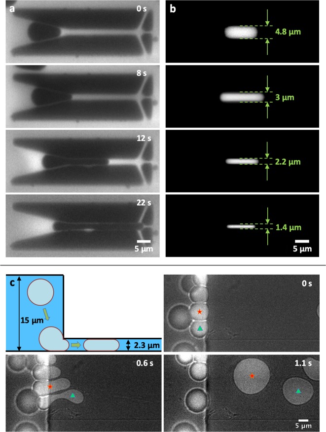
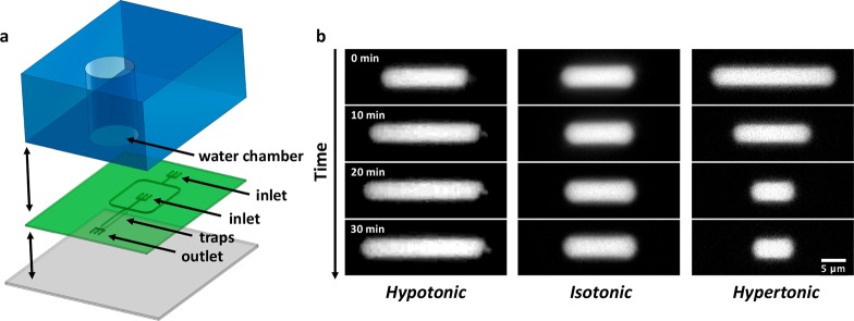
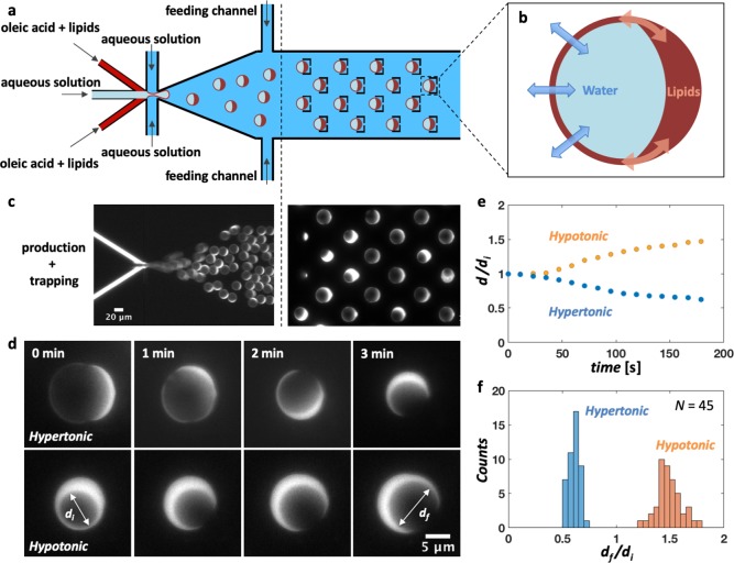
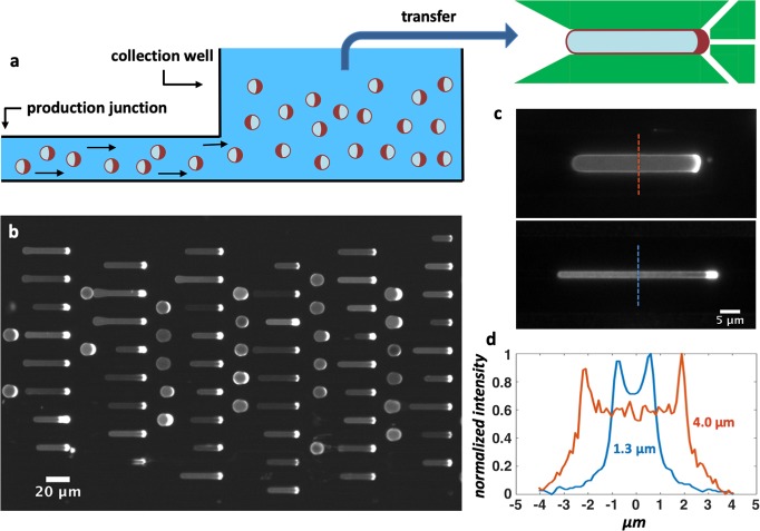
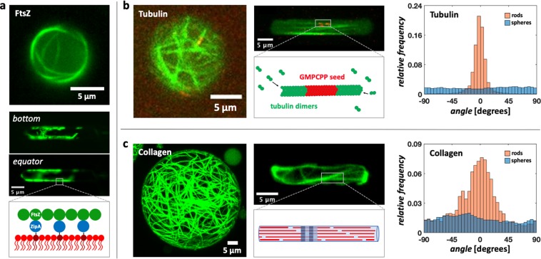
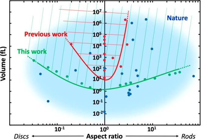
Bottom-up biology is an expanding research field that aims to understand the mechanisms underlying biological processes via in vitro assembly of their essential components in synthetic cells. As encapsulation and controlled manipulation of these elements is a crucial step in the recreation of such cell-like objects, microfluidics is increasingly used for the production of minimal artificial containers such as single-emulsion droplets, double-emulsion droplets, and liposomes. Despite the importance of cell morphology on cellular dynamics, current synthetic-cell studies mainly use spherical containers, and methods to actively shape manipulate these have been lacking. In this paper, we describe a microfluidic platform to deform the shape of artificial cells into a variety of shapes (rods and discs) with adjustable cell-like dimensions below 5 μm, thereby mimicking realistic cell morphologies. To illustrate the potential of our method, we reconstitute three biologically relevant protein systems (FtsZ, microtubules, collagen) inside rod-shaped containers and study the arrangement of the protein networks inside these synthetic containers with physiologically relevant morphologies resembling those found in living cells.

Keywords: bottom-up biology; droplets; lab-on-a-chip; liposomes; microfluidics; morphology control; synthetic cell.


Conflict of interest statement

The authors declare no competing financial interest.

Figures

Figure 1
Figure 1
Shape and size control of synthetic cells to explore the influence of confinement and geometry on cellular processes. Most current approaches to bottom-up biology encapsulate purified cellular components inside large, spherical containers. For example, on the top row, three prokaryotic key systems, which in some form are present in all kingdoms of life, are reconstituted in spherical droplets: DNA (E. coli nucleoid, blue), cytoskeletal components (FtsZ, green), and pattern formation systems (Min proteins, red). However, these key systems are, like most processes and structures inside a cell, sensitive to the confinement size and the geometry. Using a microfluidic approach (middle), we manipulate the shape and size of the initially spherical synthetic cells. In this manner, we are able to experimentally access a set of parameters which were hitherto unexplored in the field of bottom-up biology. The method offers the possibility of observing more in vivo-like dynamics for various cellular systems encapsulated inside synthetic cells (bottom).
Figure 2
Figure 2
Shape control of water-in-oil droplets via microfluidic structures. (a) Droplet loading into a tubular trap: The droplet is captured at the entrance of the trap and progressively squeezed into the confinement, assuming the imposed geometry. RhodPE lipids are dissolved in the oil phase to enhance the contrast between the oil phase, the aqueous phase, and the profile of the trap. (b) The tubular trap design offers the possibility to deform droplets into rod-shaped geometries of different dimensions. To visualize the droplets, Alexa647 fluorescent dye is encapsulated in the aqueous phase. (c) A multiheight microfluidic device is used for the deformation of spherical droplets into thin disc-shaped containers or “pancakes”. As they pass from a 15 μm to a 2 μm high channel, the spherical droplets get consequently squeezed into a disc shape. The figure shows the deformation process of two droplets, marked with a red star and green triangle. The images combine both bright-field and fluorescent signals from the Alexa647 fluorescent dye encapsulated inside the droplets.
Figure 3
Figure 3
Size control of water-in-oil droplets via a multilayer microfluidic device. (a) Schematic of the three different layers composing the device. The bottom layer (gray) consists of a PMDS-covered glass coverslip, followed by a second layer (green) of a thin PDMS membrane imprinted with the microfluidic channels and traps design. The design includes two inlet channels, the first one for the droplets and a second one for oil, which cross each other in a large T-junction. After this junction, a single large channel leads to the array of traps to capture and manipulate the droplets. The third layer (blue) is a thicker piece of PDMS containing a water chamber, placed above the array of traps. (b) Water-in-oil droplets contain Alexa647 for visualization and 200 mM KCl. Depending on the relative salt concentration between the water chamber and the droplets, different behaviors are observed over time: In hypotonic conditions (100 mM KCl in water chamber), the droplets expand (left); in isotonic conditions (200 mM KCl in the water chamber), the droplet size remains qualitatively stable (center); and in hypertonic conditions (300 mM KCl in the water chamber), the droplets shrink consistently relative to their original volume (right).
Figure 4
Figure 4
Size control of oleic acid double emulsions on-chip. (a) Design of the microfluidic device: Six channels containing an inner aqueous phase, a lipid phase, and an outer aqueous phase cross in a junction where double emulsions are produced. The inner aqueous solution blows a bubble into two streams of DOPC lipids dissolved in oleic acid. The resulting lipid film is pinched-off by the outer aqueous stream, and a double emulsion is formed. An array of traps downstream from the production junction immobilizes the double emulsions, and two additional feeding channels allow further adjustment of the outer aqueous solution forming the environment of the trapped double emulsions. (b) Schematic representation of an oleic acid double emulsion: By inducing an osmotic pressure difference, water is able to flow through the membrane to re-establish osmotic equilibrium. At the same time, the side pocket formed by the excess of lipids and solvent can serve as a reservoir for the surface to expand or shrink as required by the volume change. (c) Fluorescent image showing the production process and the trapping of oleic acid double emulsions on-chip. RhodPE fluorescent lipids allow the visualization of the lipid phase. (d) By inducing an osmotic pressure difference, it is possible to vary the size of double emulsions. Both inner aqueous and outer aqueous solutions initially contain 25 mM sucrose. After a solution containing 200 mM sucrose is flushed through the feeding channel, to re-establish osmotic equilibrium, the double emulsions consequently shrink (top). Afterward, the same batch of double emulsions is re-exposed to the original outer aqueous solution (bottom), so their volume re-expanded. (e) Size variation of double emulsions (N = 10) over time: In hypotonic or hypertonic conditions, the diameter of the double emulsions, respectively, increased or decreased over time. (f) Histogram showing the ratio of the double emulsion (N = 45) diameters measured at the end (df) and at the beginning (di) of both processes. In a hypertonic condition, the double emulsions shrink by an average factor of df/di = 0.61 ± 0.01. When back in hypotonic conditions, we measured a factor df/di = 1.49 ± 0.02.
Figure 5
Figure 5
Shape manipulation of oleic acid double emulsions on-chip. (a) Schematic cross section of the collection well: At the end of the microfluidic circuit, after the production junction, a 4 mm diameter hole is punched. The double emulsions contain 5 mM dextran to make them denser than the environment and consequently sink to the bottom of the well. After sufficient production, double emulsions are pipetted from the well and introduced into a device containing the microfluidic traps. (b) Fluorescent image showing an array of double emulsions captured in tubular traps. Thanks to their side pocket, which serves as a membrane reservoir, double emulsions are easily reshaped, so that almost all traps in the device (N = 105) contained a double emulsion. Fluorescent signal comes from RhodPE lipids in the lipid phase. (c) Zoom-in of single double emulsions in tubular traps of different dimensions: 5 μm diameter (top) and 2 μm diameter (bottom). (d) Fluorescent profiles measured at the midcell cross section of tubular double emulsions. The peaks indicate the location of the membrane and provide a measure of the width of the double emulsion.
Figure 6
Figure 6
Impact of container geometry on the organization of various protein bundle networks encapsulated inside rod-shaped droplets. (a) FtsZ filamentous bundles in spherical (top) and rod-shaped (middle) water-in-oil droplets. The FtsZ superstructures visible on the bottom plane of the rod-shaped droplet (middle) adhere to the surface of the droplet, as is also seen on the equatorial plane. A lipid monolayer containing DGS-NTA lipids (dark red) and DOPC (red) is assembled at the water–oil interface. By replacing its transmembrane tail with a His-tag, which can bind to the Ni-tag on the headgroup of DGS-NTA lipids, ZipA functions as a membrane anchor for the FtsZ filaments (bottom). FtsZ is labeled with Alexa488. (b) Microtubules grown in spherical (left) and rod-shaped droplets (middle). As shown both qualitatively in the images and quantitatively by the analysis of the fiber orientations (right), the microtubules inside spherical droplets (N = 10) grow without any strong preferential orientation, whereas in the rod-shaped droplets (N = 10), the network appears to follow the symmetry axis of the droplet. For the reconstitution of microtubules, GMPCPP stabilized seeds (labeled with rhodamine tubulin) serve as templates for the growth of microtubules through the addition of tubulin dimers in solution (bottom). Fluorescent HiLyte 488 tubulin was used to label the microtubules. (c) Collagen fibril reconstituted inside spherical- (left) and rod-shaped droplets (middle). Similar to what is observed for microtubules, the analysis of the fiber orientation (right) shows that the collagen network in spherical droplets (N = 4) remains weakly organized, but inside the rod-shaped droplets (N = 4), it re-arranges to align with the symmetry axis of the droplet. As sketched (middle-bottom), a collagen fibril is formed by the staggering of collagen triple-helix monomers (red) driven by noncovalent interactions, which give rise to a characteristic periodic pattern (blue and light-blue).
Figure 7
Figure 7
Phase diagram comparing the shape and size of various cells found in nature with the deformable artificial containers used in previous research work and those presented in this paper. Assuming roughly spheroid-like containers and cells, the morphological space is defined by the aspect ratio of the smallest and the largest axis of the containers (x-axis) and the volume (y-axis). The space is divided between rods (right), spheres (y-axis), and discs (left). In blue, an approximate cloud encircles the morphologies adopted by a selected number of living organisms (blue dots, see Table S6). The red dots represent container geometries reported previously in the field (see Table S6), with the red line showing the lower morphological boundaries achieved so far. Similarly, the green line delineates the new lower boundaries achieved within this work. Compared to previous research, we expanded the boundaries of volume and aspect ratio by 1–2 orders of magnitude. This advance enables us to cover a broader range of shapes and sizes, and it bridges the gap between artificial and natural cells.

References

    1. Randich A. M.; Brun Y. V. Molecular Mechanisms for the Evolution of Bacterial Morphologies and Growth Modes. Front. Microbiol. 2015, 6, 580.10.3389/fmicb.2015.00580. - DOI - PMC - PubMed
    1. Bisson-Filho A. W.; Zheng J.; Garner E. Archaeal Imaging: Leading the Hunt for New Discoveries. Mol. Biol. Cell 2018, 29, 1675–1681. 10.1091/mbc.E17-10-0603. - DOI - PMC - PubMed
    1. Ivakov A.; Persson S. Plant Cell Shape: Modulators and Measurements. Front. Plant Sci. 2013, 4, 439.10.3389/fpls.2013.00439. - DOI - PMC - PubMed
    1. Steinman R. M.; Cohn Z. A. Identification of a Novel Cell Type in Peripheral Lymphoid Organs of Mice. J. Exp. Med. 1973, 137, 1142–1162. 10.1084/jem.137.5.1142. - DOI - PMC - PubMed
    1. Margolin W. Sculpting the Bacterial Cell. Curr. Biol. 2009, 19, R812–R822. 10.1016/j.cub.2009.06.033. - DOI - PMC - PubMed

Publication types