

Design and Utility of a Point-of-Care Microfluidic Platform to Assess Hematocrit and Blood Coagulation
- PMID: 31105798
- PMCID: PMC6519743
- DOI: 10.1007/s12195-018-0541-z
Design and Utility of a Point-of-Care Microfluidic Platform to Assess Hematocrit and Blood Coagulation
Abstract
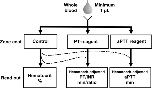
Purpose—: To develop a small volume whole blood analyzer capable of measuring the hematocrit and coagulation kinetics of whole blood.
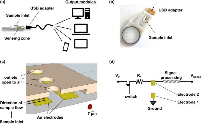
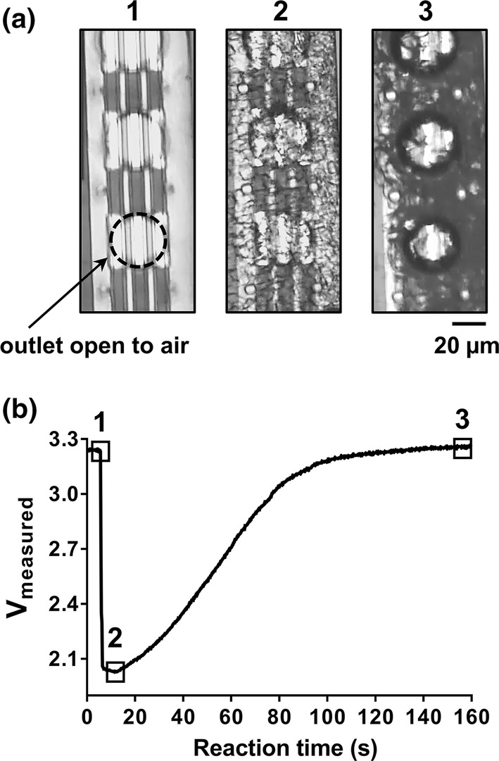
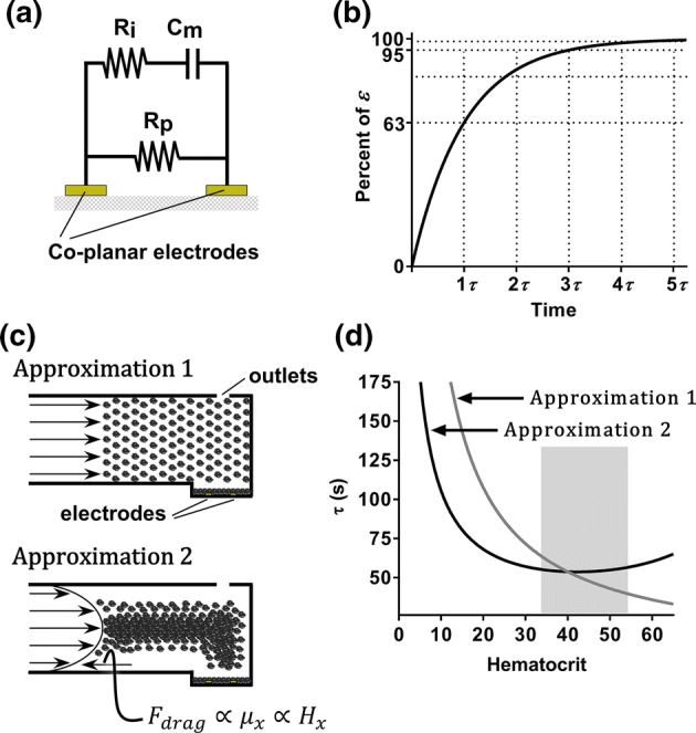
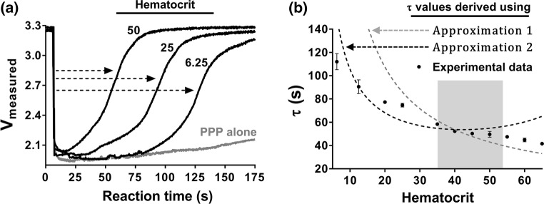
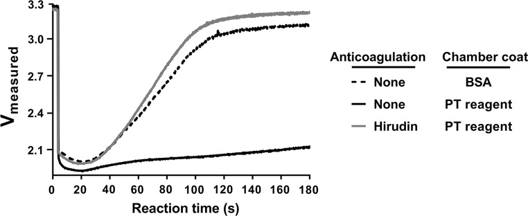
Methods and results—: A co-planar microfluidic chamber designed to facilitate self-driven capillary action across an internal electrical chip was developed and used to measure the electric parameters of whole human blood that had been anticoagulated or allowed to clot. To promote blood clotting, select chip surfaces were coated with a prothrombin time (PT) reagent containing lipidated tissue factor (TF), which activates the extrinsic pathway of coagulation to promote thrombin generation and fibrin formation. Whole human blood was added to the microfluidic device, and voltage changes within the platform were measured and interpreted using basic resistor-capacitor (RC) circuit and fluid dynamics theory. Upon wetting of the sensing zone, a circuit between two co-planar electrodes within the sensing zone was closed to generate a rapid voltage drop from baseline. The voltage then rose due to sedimentation of red blood cells (RBC) in the sensing zone. For anticoagulated blood samples, the time for the voltage to return to baseline was dependent on hematocrit. In the presence of coagulation, the initiation of fibrin formation in the presence of the PT reagent prevented the return of voltage to baseline due to the reduced packing of RBCs in the sensing zone.
Conclusions—: The technology presented in this study has potential for monitoring the hematocrit and coagulation parameters of patient samples using a small volume of whole blood, suggesting it may hold clinical utility as a point-of-care test.
Keywords: Biorheology; Coagulation; Electrical engineering; Hematocrit; Whole blood testing.
Conflict of interest statement
CONFLICT OF INTEREST HP Inc. has pending patents for microfluidic device and chip technology concept and software described. R.M. White was employed by HP, Inc. during this study. J. Zilberman-Rudenko, D.A. Zilberman, H.H.S. Lakshmanan, R.A. Rigg, J.J. Shatzel, J. Maddala and O.J.T. McCarty have no conflicts of interests. Potential conflicts of interest have been reviewed and managed by the Oregon Health and Science University Conflict of Interest in Research Committee.
Figures
Similar articles
-
Real-time electrical impedimetric monitoring of blood coagulation process under temperature and hematocrit variations conducted in a microfluidic chip.PLoS One. 2013 Oct 7;8(10):e76243. doi: 10.1371/journal.pone.0076243. eCollection 2013. PLoS One. 2013. PMID: 24116099 Free PMC article.
-
Coagulation Testing in the Core Laboratory.Lab Med. 2017 Nov 8;48(4):295-313. doi: 10.1093/labmed/lmx050. Lab Med. 2017. PMID: 29126301 Review.
-
Factor XI enhances fibrin generation and inhibits fibrinolysis in a coagulation model initiated by surface-coated tissue factor.Blood Coagul Fibrinolysis. 2006 Jun;17(4):251-7. doi: 10.1097/01.mbc.0000224843.33216.5f. Blood Coagul Fibrinolysis. 2006. PMID: 16651866
-
Additive roles of platelets and fibrinogen in whole-blood fibrin clot formation upon dilution as assessed by thromboelastometry.Thromb Haemost. 2014 Mar 3;111(3):447-57. doi: 10.1160/TH13-06-0493. Epub 2013 Nov 21. Thromb Haemost. 2014. PMID: 24258426
-
Prehospital coagulation monitoring of resuscitation with point-of-care devices.Shock. 2014 May;41 Suppl 1:26-9. doi: 10.1097/SHK.0000000000000108. Shock. 2014. PMID: 24365883 Review.
Cited by
-
Basic science research opportunities in thrombosis and hemostasis: Communication from the SSC of the ISTH.J Thromb Haemost. 2022 Jun;20(6):1496-1506. doi: 10.1111/jth.15718. Epub 2022 Apr 22. J Thromb Haemost. 2022. PMID: 35352482 Free PMC article.
-
Evolving Paradigm of Prothrombin Time Diagnostics with Its Growing Clinical Relevance towards Cardio-Compromised and COVID-19 Affected Population.Sensors (Basel). 2021 Apr 9;21(8):2636. doi: 10.3390/s21082636. Sensors (Basel). 2021. PMID: 33918646 Free PMC article. Review.
-
Development of a Microfluidic Viscometer for Non-Newtonian Blood Analog Fluid Analysis.Bioengineering (Basel). 2024 Dec 20;11(12):1298. doi: 10.3390/bioengineering11121298. Bioengineering (Basel). 2024. PMID: 39768116 Free PMC article.
-
Fully printed prothrombin time sensor for point-of-care testing.Biosens Bioelectron. 2021 Jan 15;172:112770. doi: 10.1016/j.bios.2020.112770. Epub 2020 Oct 26. Biosens Bioelectron. 2021. PMID: 33157410 Free PMC article.
-
Microfluidic-Based Novel Optical Quantification of Red Blood Cell Concentration in Blood Flow.Bioengineering (Basel). 2022 Jun 8;9(6):247. doi: 10.3390/bioengineering9060247. Bioengineering (Basel). 2022. PMID: 35735490 Free PMC article.
References
-
- Ashrafuzzaman, M., and J. Tuszynski. Structure of membranes. In: Membrane Biophysics. Heidelberg: Springer, 2012, pp. 9–30.
-
- Billett HH. Hemoglobin and hematocrit. In: Walker HK, Hall WD, Hurst JW, editors. Clinical Methods: The History, Physical, and Laboratory Examinations. 3. Boston: Butterworths; 1990. - PubMed
Grants and funding
LinkOut - more resources
Full Text Sources
Other Literature Sources
Miscellaneous
