. 2019 Apr;6(2):025006.
doi: 10.1117/1.JMI.6.2.025006. Epub 2019 May 15.

Preclinical evaluation of an integrated robotic system for magnetic resonance imaging guided shoulder arthrography

Affiliations

Preclinical evaluation of an integrated robotic system for magnetic resonance imaging guided shoulder arthrography

Niravkumar Patel et al. J Med Imaging (Bellingham). 2019 Apr.

Abstract

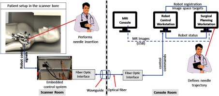
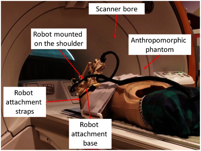
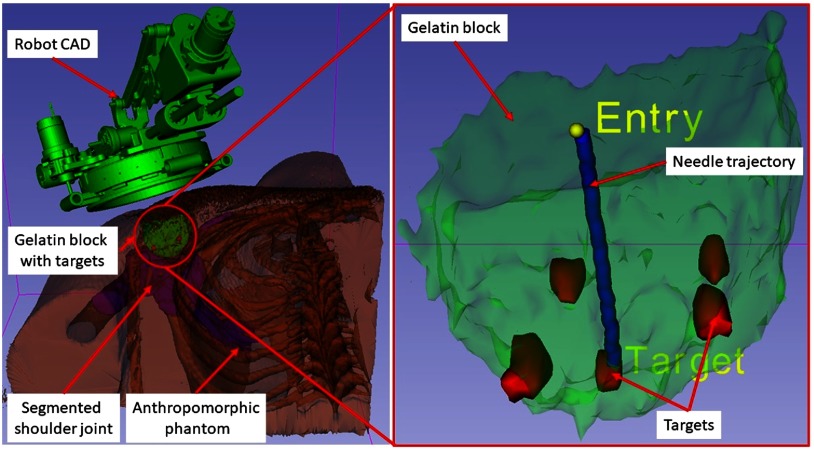
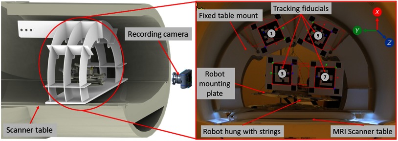
Shoulder arthrography is a diagnostic procedure which involves injecting a contrast agent into the joint space for enhanced visualization of anatomical structures. Typically, a contrast agent is injected under fluoroscopy or computed tomography (CT) guidance, resulting in exposure to ionizing radiation, which should be avoided especially in pediatric patients. The patient then waits for the next available magnetic resonance imaging (MRI) slot for obtaining high-resolution anatomical images for diagnosis, which can result in long procedure times. Performing the contrast agent injection under MRI guidance could overcome both these issues. However, it comes with the challenges of the MRI environment including high magnetic field strength, limited ergonomic patient access, and lack of real-time needle guidance. We present the development of an integrated robotic system to perform shoulder arthrography procedures under intraoperative MRI guidance, eliminating fluoroscopy/CT guidance and patient transportation from the fluoroscopy/CT room to the MRI suite. The average accuracy of the robotic manipulator in benchtop experiments is 0.90 mm and 1.04 deg, whereas the average accuracy of the integrated system in MRI phantom experiments is 1.92 mm and 1.28 deg at the needle tip. Based on the American Society for Testing and Materials (ASTM) tests performed, the system is classified as MR conditional.

Keywords: image-guided; magnetic resonance imaging; robot; shoulder arthrography.


Figures

Fig. 1
Fig. 1
System block diagram showing all the components, their layout in the operating room, and the data flow between them.
Fig. 2
Fig. 2
Robot CAD model showing the DOFs, robot coordinate system, and sterile stylet for needle insertion.
Fig. 3
Fig. 3
Interface of 3-D Slicer, showing planning and navigation information, and showing four fiducial markers for registering robot to the scanner coordinate system.
Fig. 4
Fig. 4
Proposed clinical workflow showing various steps for the robot-assisted, MRI-guided shoulder arthrography procedure. Procedure is divided into four phases, on the left of each activity shows what/who are involved for that activity, while, for each phase, measured average time is displayed on the right. Activities shown in red are not considered for the phantom studies; they will be considered for the cadaver and patient trials.
Fig. 5
Fig. 5
Benchtop experimental setup showing optical tracking reference frame and robot pose tracking frame.
Fig. 6
Fig. 6
Experimental setup showing the robot attached on the shoulder of an anthropomorphic phantom in the scanner bore for accuracy assessment.
Fig. 7
Fig. 7
A 3-D Slicer scene for one of the targeting attempts showing on the left: segmented 3-D volume of the anthropomorphic phantom, embedded gelatin block for targeting, and robot CAD overlay and on the right: close-up view of the gelatin block, five target locations, planned target and entry points, and needle trajectory segmented form a confirmation image set.
Fig. 8
Fig. 8
Experimental setup showing the robot hanging with the support of strings inside the scanner bore for performing ASTM tests: (1) magnetically induced displacement force (test method F2052), (2) magnetically induced torque (test method F2213).

References

    1. Patel N. A., et al. , “System integration and preliminary clinical evaluation of a robotic system for MRI-guided transperineal prostate biopsy,” J. Med. Rob. Res. 4(1), 1950001 (2018).10.1142/S2424905X19500016 - DOI - PMC - PubMed
    1. Krieger A., et al. , “Development and evaluation of an actuated MRI-compatible robotic system for MRI-guided prostate intervention,” IEEE/ASME Trans. Mechatron. 18(1), 273–284 (2013).IATEFW10.1109/TMECH.2011.2163523 - DOI - PMC - PubMed
    1. Su H., et al. , “Piezoelectrically actuated robotic system for MRI-guided prostate percutaneous therapy,” IEEE/ASME Trans. Mechatron. 20(4), 1920–1932 (2015).IATEFW10.1109/TMECH.2014.2359413 - DOI - PMC - PubMed
    1. Eslami S., et al. , “In-bore prostate transperineal interventions with an MRI-guided parallel manipulator: system development and preliminary evaluation,” Int. J. Med. Rob. Comput. Assisted Surg. 12(2), 199–213 (2016).10.1002/rcs.1671 - DOI - PMC - PubMed
    1. Stoianovici D., et al. , “MR safe robot, FDA clearance, safety and feasibility prostate biopsy clinical trial,” IEEE/ASME Trans. Mechatron. 22, 115–126 (2017).IATEFW10.1109/TMECH.2016.2618362 - DOI - PMC - PubMed