. 2019 Jun 5;5(6):eaav8002.
doi: 10.1126/sciadv.aav8002. eCollection 2019 Jun.

Raising fluid walls around living cells

Affiliations

Raising fluid walls around living cells

Cristian Soitu et al. Sci Adv. .

Abstract

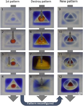
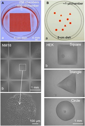
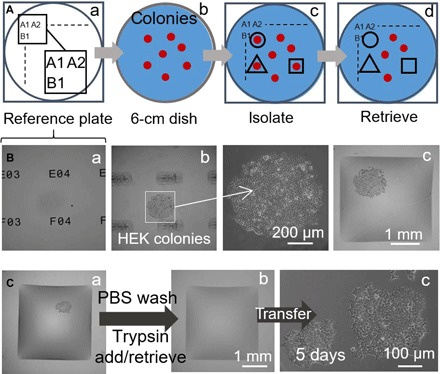
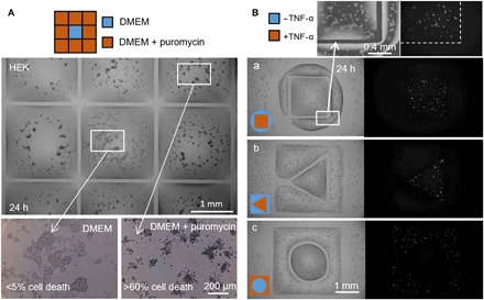
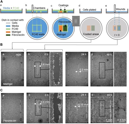
An effective transformation of the cell culture dishes that biologists use every day into microfluidic devices would open many avenues for miniaturizing cell-based workflows. In this article, we report a simple method for creating microfluidic arrangements around cells already growing on the surface of standard petri dishes, using the interface between immiscible fluids as a "building material." Conventional dishes are repurposed into sophisticated microfluidic devices by reshaping, on demand, the fluid structures around living cells. Moreover, these microfluidic arrangements can be further reconfigured during experiments, which is impossible with most existing microfluidic platforms. The method is demonstrated using workflows involving cell cloning, the selection of a particular clone from among others in a dish, drug treatments, and wound healing. The versatility of the approach and its biologically friendly aspects may hasten uptake by biologists of microfluidics, so the technology finally fulfills its potential.


Figures

Fig. 1
Fig. 1. Chamber construction.
(A) Principle. Dulbecco’s modified Eagle’s medium (DMEM) + 10% fetal bovine serum (FBS) is added to a virgin petri dish, and most of the medium is removed to leave a thin film covering the bottom, which is overlaid with FC40. The stylus is moved across the bottom to create a microfluidic arrangement. When complete, the initial volume of DMEM + 10% FBS will be divided into two parts separated by a continuous liquid wall of FC40 pinned to the substrate. (B) Different patterns. (a) Forming equally spaced vertical and horizontal lines creates an array (32 × 32; 1-mm spacing). Next, 60 nl of blue dye is added by the printer to selected chambers; peripheral chambers receive blue dye to give the blue square, and internal ones give the word “OXFORD.” The magnification (right) shows individual chambers without and with dye. (b) A similar pattern is created by forming two squares (one slightly larger than the other) with the stylus and then adding dye manually to the space in between; each letter is made by forming its sides and again manually filling the interior. The magnification shows that the letter “F” is one continuous body of liquid. Photo credit: Cristian Soitu, University of Oxford.
Fig. 2
Fig. 2. Reconfiguring microfluidic arrangements.
Images show frames from movie S1. (1) An initial pattern is printed: a circle (radius, 1.5 mm) inside a triangle (side, 7 mm) inside a square (side, 9 mm). (2 to 4) Different dyes are added to each compartment (1.5 μl of red dye, 1.5 μl of yellow dye, and 5 μl of blue dye); dyes are confined within FC40 walls. (5) More yellow dye is added to the circle. (6) After adding 3 μl of yellow dye, the circular pinning line ruptures and contents spill into the triangle. (7) After adding 24 μl, the triangular pinning line ruptures and contents spill into the square. (8) Sixty microliters is withdrawn from the square. (9) A new pattern is printed—a triangle (side, 4.5 mm) in a circle (radius, 3.3 mm)—in the initial square. (10 to 12) Colored dyes are added to the three different compartments as before. Photo credit: Cristian Soitu, University of Oxford.
Fig. 3
Fig. 3. Building walls before or after cloning cells.
(A) Building walls before plating single cells in individual chambers. After making grids (16 × 16, 2-mm spacing; 6-cm dishes), dye or cells (NM18) were added by the printer. (a) Red dye (600 nl) is added to each chamber to illustrate the grid used. (b) Medium (600 nl) containing 0.2 cells is added to each chamber (so only a few chambers receive one cell), dishes are incubated (8 days), and chambers are imaged; the central chamber contains one colony (see magnification). (B) Building walls around living clones. (a) Red dye (1 μl) is added to various shapes printed in a dish; the dye is added to aid visualization (see also movie S2). (b) HEK cells were plated in a dish (density, ~1 cell/cm2) and allowed to grow for 8 days into colonies. Next, most of the medium is removed to leave a thin film on the surface, FC40 is added, various shapes are drawn around colonies, each chamber is filled with 1 μl of medium using the printer, and images are collected. The three images come from different dishes. Photo credit: Cristian Soitu, University of Oxford
Fig. 4
Fig. 4. Semi-automating selective clone picking (HEK cells).
The printer adds/removes a microliter to/from chambers at different stages. (A) Approach. (a) Locations on a glass “reference plate” are marked by unique identifiers (i.e., A1, A2 …, B1…). (b) A 6-cm dish with colonies (red) is placed on the reference plate. (c) After recording colony locations and inputting them into a script, fluid walls are printed around selected clones (black lines). (d) Clones are retrieved from these chambers. (B) Isolating a clone. HEK cells were plated at low density (~1 cell/cm2) and grown (8 days) into clones, the dish was placed on a reference plate, and walls were built around selected clones. Three different z-axis views of one clone are shown. (a) Reference plate with unique identifiers in focus. (b) Colony in focus (identifiers out of focus) with magnification. (c) Colony after building surrounding walls. (C) Clone picking. (a) Square wall built around one living colony. The printer washes cells by adding/retrieving 1 μl of PBS; it then adds 1 μl of trypsin. (b) The dish is incubated (37°C; 5 min) to detach cells from the surface, and the printer retrieves 1 μl containing the cell-rich suspension (and transfers it to a microcentrifuge tube) to leave the now-empty chamber. (c) Retrieved cells are plated manually in a 12-well microtiter plate and grown conventionally for 5 days; cells attach and grow.
Fig. 5
Fig. 5. Two drug treatments side by side with untreated cells.
Fluid walls were built around HEK cells (300,000 cells; 6-cm dish) grown for 24 hours. (A) Puromycin (3 × 3 grid; 2 mm × 2 mm chambers). The printer adds 1 μl of medium to the central chamber and 1 μl of medium + puromycin to peripheral ones (final concentration, 10 μg/ml), as indicated in the cartoon. Cell viability is assessed after incubation (37°; 24 hours) using a trypan blue exclusion assay. Cells in outer chambers are dead (more than 60% in each one), whereas those in the central one remain alive (less than 5% cell death). This assay has been replicated three times. (B) TNF-α. Pairs of chambers with distinct shapes are printed, one surrounding the other. The printer adds 0.5 μl of medium ± TNF-α (final concentration, 10 ng/ml) to one or other volume (as in cartoons). As cells encode a GFP-reporter gene controlled by a promoter switched on by TNF-α, they fluoresce green on exposure to the cytokine. Fluorescence images show that only cells in the treated volume fluoresce green. Volume pairs had the following dimensions: (a) square (side, 1.8 mm) in circle (radius, 1.75 mm); (b) triangle (side, 1 mm) in square (side, 3.5 mm); (c) circle (radius, 1 mm) in square (side, 3.5 mm).
Fig. 6
Fig. 6. A proof-of-concept wound-healing assay using one dish precoated with Matrigel and fibronectin in different regions.
(A) Cartoon illustrating workflow. (a) A thin layer of medium is overlaid with FC40. (b) Two chambers (3 mm × 4 mm each) are printed side by side. (c) Surfaces in chambers are coated with Matrigel or fibronectin (2 μl; final concentration of 1 μg/cm2; 1 hour); the inset shows an image of one chamber. Fluid walls are now destroyed, and the dish is washed with 3 ml of medium to remove unattached coatings. (d) HEK cells (600,000) are plated in the dish. (e) After 24 hours, cells have formed a monolayer, and a wound (0.4 mm × 2 mm) is created by scraping the stylus over the surface to remove cells in its path. Healing of the wound is now monitored microscopically. (B and C) Images of wounds in monolayers grown on Matrigel or fibronectin. (a and b) Immediately before and after wounding (some droplets of FC40 remain where walls originally stood). (c) After 24 hours, cell growth reduces wound widths to <0.2 mm and <0.15 mm with Matrigel and fibronectin, respectively. (d) By 48 hours, wounds have completely healed.

References

    1. J. Berthier, K. A. Brakke, The Physics of Microdroplets (John Wiley & Sons, 2012).
    1. Sackmann E. K., Fulton A. L., Beebe D. J., The present and future role of microfluidics in biomedical research. Nature 507, 181–189 (2014). - PubMed
    1. Berthier E., Young E. W. K., Beebe D., Engineers are from PDMS-land, biologists are from Polystyrenia. Lab Chip 12, 1224–1237 (2012). - PubMed
    1. Casavant B. P., Berthier E., Theberge A. B., Berthier J., Montanez-Sauri S. I., Bischel L. L., Brakke K., Hedman C. J., Bushman W., Keller N. P., Beebe D. J., Suspended microfluidics. Proc. Natl. Acad. Sci. U.S.A. 110, 10111–10116 (2013). - PMC - PubMed
    1. Visser C. W., Kamperman T., Karbaat L. P., Lohse D., Karperien M., In-air microfluidics enables rapid fabrication of emulsions, suspensions, and 3D modular (bio)materials. Sci. Adv. 4, eaao1175 (2018). - PMC - PubMed

Publication types