

Neuromorphic Stereo Vision: A Survey of Bio-Inspired Sensors and Algorithms
- PMID: 31191287
- PMCID: PMC6546825
- DOI: 10.3389/fnbot.2019.00028
Neuromorphic Stereo Vision: A Survey of Bio-Inspired Sensors and Algorithms
Abstract
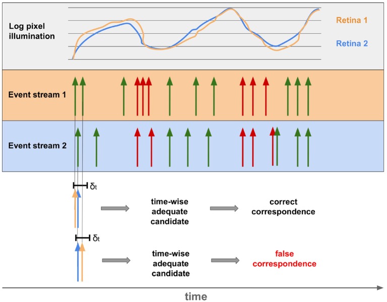
Any visual sensor, whether artificial or biological, maps the 3D-world on a 2D-representation. The missing dimension is depth and most species use stereo vision to recover it. Stereo vision implies multiple perspectives and matching, hence it obtains depth from a pair of images. Algorithms for stereo vision are also used prosperously in robotics. Although, biological systems seem to compute disparities effortless, artificial methods suffer from high energy demands and latency. The crucial part is the correspondence problem; finding the matching points of two images. The development of event-based cameras, inspired by the retina, enables the exploitation of an additional physical constraint-time. Due to their asynchronous course of operation, considering the precise occurrence of spikes, Spiking Neural Networks take advantage of this constraint. In this work, we investigate sensors and algorithms for event-based stereo vision leading to more biologically plausible robots. Hereby, we focus mainly on binocular stereo vision.
Keywords: bio-inspired 3D-perception; brain-inspired robotics; cooperative algorithms; event-based technologies; human-like vision; neuromorphic visual sensors.
Figures
Similar articles
-
A Spike-Based Neuromorphic Architecture of Stereo Vision.Front Neurorobot. 2020 Nov 13;14:568283. doi: 10.3389/fnbot.2020.568283. eCollection 2020. Front Neurorobot. 2020. PMID: 33304262 Free PMC article.
-
A Benchmark Environment for Neuromorphic Stereo Vision.Front Robot AI. 2021 May 19;8:647634. doi: 10.3389/frobt.2021.647634. eCollection 2021. Front Robot AI. 2021. PMID: 34095240 Free PMC article.
-
A spiking neural network model of 3D perception for event-based neuromorphic stereo vision systems.Sci Rep. 2017 Jan 12;7:40703. doi: 10.1038/srep40703. Sci Rep. 2017. PMID: 28079187 Free PMC article.
-
Event-Based Vision: A Survey.IEEE Trans Pattern Anal Mach Intell. 2022 Jan;44(1):154-180. doi: 10.1109/TPAMI.2020.3008413. Epub 2021 Dec 7. IEEE Trans Pattern Anal Mach Intell. 2022. PMID: 32750812 Review.
-
Scaling up liquid state machines to predict over address events from dynamic vision sensors.Bioinspir Biomim. 2017 Sep 1;12(5):055001. doi: 10.1088/1748-3190/aa7663. Bioinspir Biomim. 2017. PMID: 28569669 Review.
Cited by
-
An Extended Modular Processing Pipeline for Event-Based Vision in Automatic Visual Inspection.Sensors (Basel). 2021 Sep 13;21(18):6143. doi: 10.3390/s21186143. Sensors (Basel). 2021. PMID: 34577349 Free PMC article.
-
A Spike-Based Neuromorphic Architecture of Stereo Vision.Front Neurorobot. 2020 Nov 13;14:568283. doi: 10.3389/fnbot.2020.568283. eCollection 2020. Front Neurorobot. 2020. PMID: 33304262 Free PMC article.
-
Hemispherical Retina Emulated by Plasmonic Optoelectronic Memristors with All-Optical Modulation for Neuromorphic Stereo Vision.Adv Sci (Weinh). 2024 Sep;11(36):e2405160. doi: 10.1002/advs.202405160. Epub 2024 Jul 25. Adv Sci (Weinh). 2024. PMID: 39049682 Free PMC article.
-
A Benchmark Environment for Neuromorphic Stereo Vision.Front Robot AI. 2021 May 19;8:647634. doi: 10.3389/frobt.2021.647634. eCollection 2021. Front Robot AI. 2021. PMID: 34095240 Free PMC article.
-
Retina-inspired narrowband perovskite sensor array for panchromatic imaging.Sci Adv. 2023 Apr 14;9(15):eade2338. doi: 10.1126/sciadv.ade2338. Epub 2023 Apr 14. Sci Adv. 2023. PMID: 37058567 Free PMC article.
References
-
- Andreopoulos A., Kashyap H. J., Nayak T. K., Amir A., Flickner M. D. (2018). A low power, high throughput, fully event-based stereo system, in The IEEE Conference on Computer Vision and Pattern Recognition (CVPR). (Salt Lake City, UT: ), 7532–7542.
-
- Barnard S. T., Fischler M. A. (1982). Computational stereo. ACM Comput. Surv. 14, 553–572. 10.1145/356893.356896 - DOI
Publication types
LinkOut - more resources
Full Text Sources