

Development of a magnetic composite material for measurement of residual limb displacements in prosthetic sockets
- PMID: 31191930
- PMCID: PMC6453102
- DOI: 10.1177/2055668318763481
Development of a magnetic composite material for measurement of residual limb displacements in prosthetic sockets
Abstract
Introduction: Wearable limb-socket displacement sensors may help patients and prosthetists identify a deteriorating socket fit and justify the need for repair or replacement.
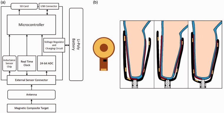
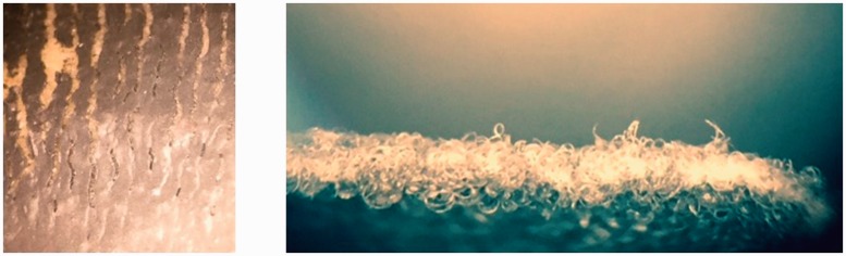
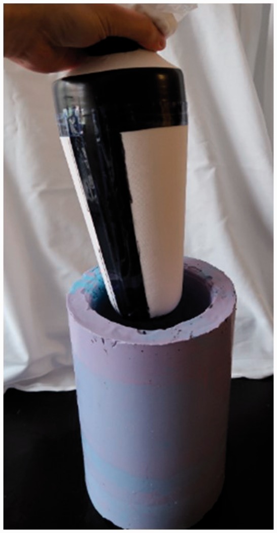
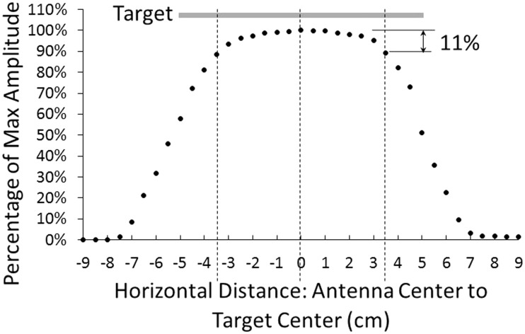
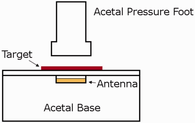
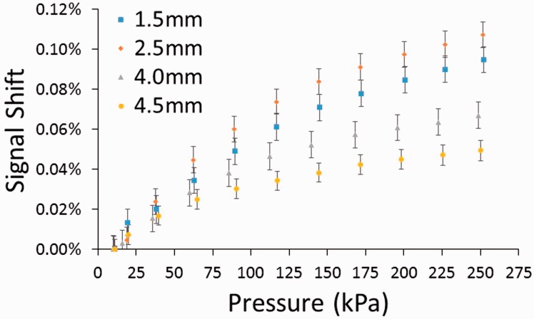
Methods: A novel sensor using an inductive sensing modality was developed to detect limb-to-socket distances. Key detection elements were a coil antenna placed in the socket wall and a magnetic composite sheath worn over the outside of the prosthesis user's elastomeric liner. The sheath was a nylon or cotton prosthetic stocking coated with a polyurethane composite. The polyurethane composite contained embedded iron particles (75 wt%).
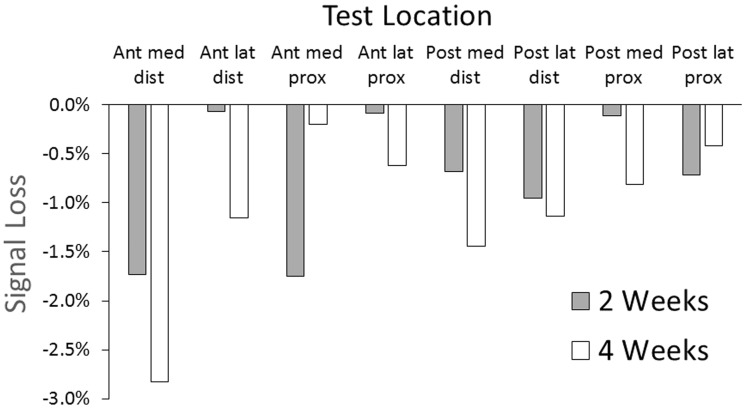
Results: Brushing γ-glycidoxypropyltriethoxysilane onto the sheath fabric, coating it first with unfilled polyurethane and then iron-filled polyurethane, enhanced bonding between the sheath and the composite and overcame mechanical degradation problems. A γ-glycidoxypropyltriethoxysilane-rich fumed silica layer applied to the outside of the sheath reduced friction and improved durability. Field testing demonstrated less than a 3% signal degradation from four weeks of field use.
Conclusions: The developed wearable displacement sensor meets durability and performance needs, and is ready for large-scale clinical testing.
Keywords: Amputees; biomechanical testing/analysis; limb prosthetics; rehabilitation; sensor design.
Conflict of interest statement
The author(s) declared no potential conflicts of interest with respect to the research, authorship, and/or publication of this article.
Figures
Similar articles
-
An Inductive Sensing System to Measure In-Socket Residual Limb Displacements for People Using Lower-Limb Prostheses.Sensors (Basel). 2018 Nov 9;18(11):3840. doi: 10.3390/s18113840. Sensors (Basel). 2018. PMID: 30423932 Free PMC article.
-
Thin Magnetically Permeable Targets for Inductive Sensing: Application to Limb Prosthetics.Sensors (Basel). 2019 Sep 19;19(18):4041. doi: 10.3390/s19184041. Sensors (Basel). 2019. PMID: 31546816 Free PMC article.
-
Using mechanical testing to assess the effect of lower-limb prosthetic socket texturing on longitudinal suspension.PLoS One. 2020 Aug 19;15(8):e0237841. doi: 10.1371/journal.pone.0237841. eCollection 2020. PLoS One. 2020. PMID: 32813733 Free PMC article.
-
Design of lower limb prosthetic sockets: a review.Expert Rev Med Devices. 2022 Jan;19(1):63-73. doi: 10.1080/17434440.2022.2020094. Epub 2021 Dec 31. Expert Rev Med Devices. 2022. PMID: 34932435 Review.
-
Techniques for Interface Stress Measurements within Prosthetic Sockets of Transtibial Amputees: A Review of the Past 50 Years of Research.Sensors (Basel). 2016 Jul 20;16(7):1119. doi: 10.3390/s16071119. Sensors (Basel). 2016. PMID: 27447646 Free PMC article. Review.
Cited by
-
An Inductive Sensing System to Measure In-Socket Residual Limb Displacements for People Using Lower-Limb Prostheses.Sensors (Basel). 2018 Nov 9;18(11):3840. doi: 10.3390/s18113840. Sensors (Basel). 2018. PMID: 30423932 Free PMC article.
-
Thin Magnetically Permeable Targets for Inductive Sensing: Application to Limb Prosthetics.Sensors (Basel). 2019 Sep 19;19(18):4041. doi: 10.3390/s19184041. Sensors (Basel). 2019. PMID: 31546816 Free PMC article.
-
Prosthetists' perceptions of information obtained from a lower limb prosthesis monitoring system: a pilot study.J Prosthet Orthot. 2019 Apr;31(2):112-120. doi: 10.1097/JPO.0000000000000203. J Prosthet Orthot. 2019. PMID: 31571806 Free PMC article.
-
Reported Outcome Measures in Studies of Real-World Ambulation in People with a Lower Limb Amputation: A Scoping Review.Sensors (Basel). 2022 Mar 14;22(6):2243. doi: 10.3390/s22062243. Sensors (Basel). 2022. PMID: 35336412 Free PMC article.
References
-
- Grevsten S, Eriksson U. Stump-socket contact and skeletal displacement in a suction patellar-tendon bearing prosthesis. J Bone Joint Surg 1974; 56: 1692–1696. - PubMed
-
- Grevsten S. Ideas on the suspension of the below-knee prosthesis. Prosthet Orthot Int 1978; 2: 3–7. - PubMed
-
- Commean PK, Smith KE, Vannier MW. Lower extremity residual limb slippage within the prosthesis. Arch Phys Med Rehabil 1997; 78: 476–485. - PubMed
-
- Fernie G, Holliday P. Volume fluctuations in the residual limbs of lower limb amputees. Arch Phys Med Rehabil 1982; 63: 162–165. - PubMed
LinkOut - more resources
Full Text Sources
Other Literature Sources
