

A Comprehensive Study of Ultrasound Transducer Characteristics in Microscopic Ultrasound Neuromodulation
- PMID: 31199268
- PMCID: PMC6883411
- DOI: 10.1109/TBCAS.2019.2922027
A Comprehensive Study of Ultrasound Transducer Characteristics in Microscopic Ultrasound Neuromodulation
Abstract
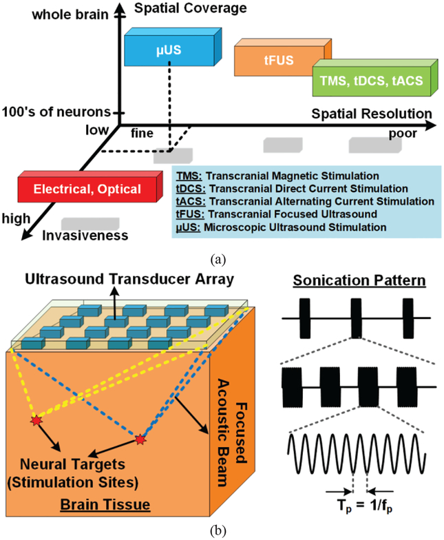
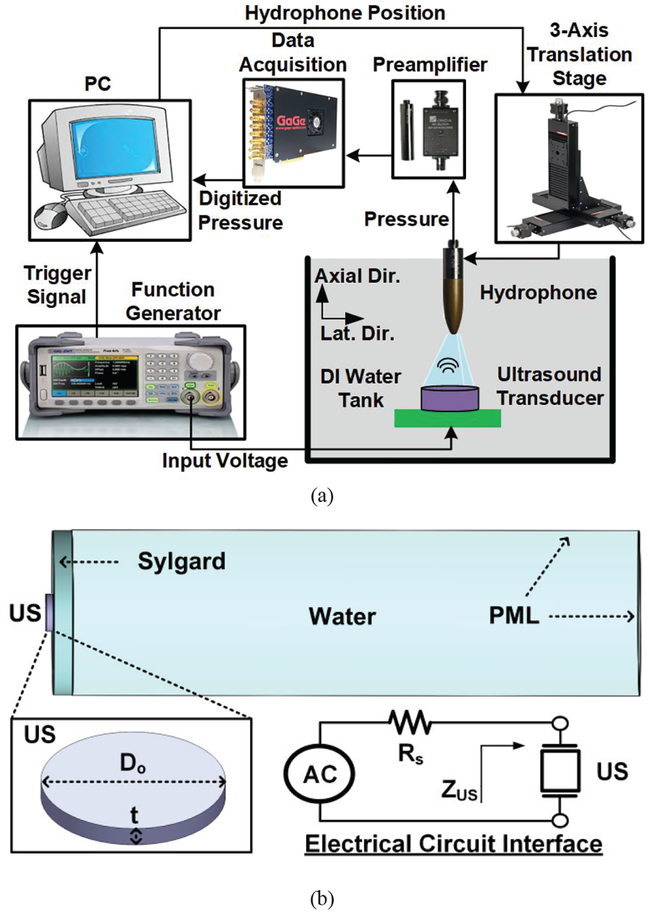
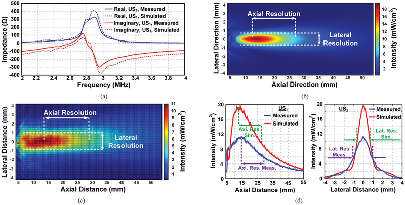
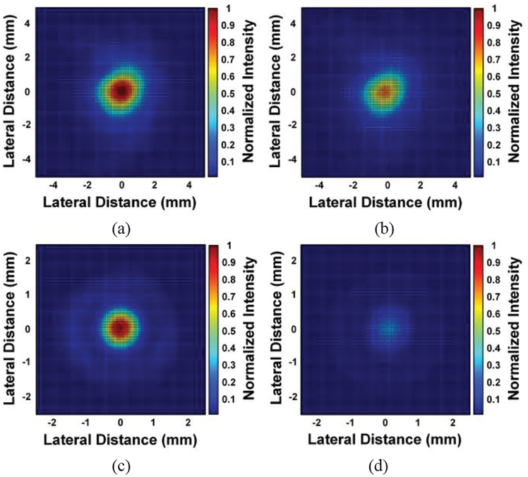
In order to improve the spatial resolution of transcranial focused ultrasound stimulation (tFUS), we have recently proposed microscopic ultrasound stimulation (μUS). In μUS, either an electronically phased array of ultrasound transducers or several millimeter-sized focused transducers are placed on the brain surface or sub-millimeter-sized transducers are implanted inside the brain tissue to steer and deliver a focused ultrasound pressure directly to the neural target. A key element in both tFUS and μUS is the ultrasound transducer that converts electrical power to acoustic pressure. The literature lacks a comprehensive study (in a quantitative manner) of the transducer characteristics, such as dimension, focusing, acoustic matching, backing material, and sonication frequency (fp), in the μUS. This paper studies the impact of these design parameters on the acoustic beam profile of millimeter-sized transducers with the emphasis on the stimulation spatial resolution and energy efficiency, which is defined as the μUS figure-of-merit (FoM). For this purpose, disc-shaped focused and unfocused piezoelectric (PZT-5A) transducers with different dimension (diameter, thickness), backing material (PCB, air) and acoustic matching in the frequency range of 2.2-9.56 MHz were fabricated. Our experimental studies with both water and sheep brain phantom medium demonstrate that acoustically matched focused transducers with high quality factor are desirable for μUS, as they provide fine spatial resolution and high acoustic intensities with low input electrical power levels (i.e., high FoM).
Figures


Similar articles
-
Design and Optimization of Ultrasound Phased Arrays for Large-Scale Ultrasound Neuromodulation.IEEE Trans Biomed Circuits Syst. 2021 Dec;15(6):1454-1466. doi: 10.1109/TBCAS.2021.3133133. Epub 2022 Feb 17. IEEE Trans Biomed Circuits Syst. 2021. PMID: 34874867 Free PMC article.
-
Skull Impact on the Ultrasound Beam Profile of Transcranial Focused Ultrasound Stimulation.Annu Int Conf IEEE Eng Med Biol Soc. 2019 Jul;2019:5188-5191. doi: 10.1109/EMBC.2019.8857269. Annu Int Conf IEEE Eng Med Biol Soc. 2019. PMID: 31947027
-
Numerical and experimental evaluation of low-intensity transcranial focused ultrasound wave propagation using human skulls for brain neuromodulation.Med Phys. 2023 Jan;50(1):38-49. doi: 10.1002/mp.16090. Epub 2022 Nov 24. Med Phys. 2023. PMID: 36342303 Free PMC article.
-
A Review of Ultrasound Neuromodulation Technologies.IEEE Trans Biomed Circuits Syst. 2023 Oct;17(5):1084-1096. doi: 10.1109/TBCAS.2023.3299750. Epub 2023 Nov 21. IEEE Trans Biomed Circuits Syst. 2023. PMID: 37506009 Review.
-
Safety Review and Perspectives of Transcranial Focused Ultrasound Brain Stimulation.Brain Neurorehabil. 2021 Mar 17;14(1):e4. doi: 10.12786/bn.2021.14.e4. eCollection 2021 Mar. Brain Neurorehabil. 2021. PMID: 36742103 Free PMC article. Review.
Cited by
-
Low-Cost Scalable PCB-Based 2-D Transducer Arrays for Volumetric Photoacoustic Imaging.IEEE Sens J. 2024 Feb 15;24(4):4380-4386. doi: 10.1109/JSEN.2023.3344824. Epub 2023 Dec 27. IEEE Sens J. 2024. PMID: 38505656 Free PMC article.
-
Design and Optimization of Ultrasonic Links With Phased Arrays for Wireless Power Transmission to Biomedical Implants.IEEE Trans Biomed Circuits Syst. 2022 Feb;16(1):64-78. doi: 10.1109/TBCAS.2022.3140591. Epub 2022 May 9. IEEE Trans Biomed Circuits Syst. 2022. PMID: 34986100 Free PMC article.
-
Recent Advances in Transducers for Intravascular Ultrasound (IVUS) Imaging.Sensors (Basel). 2021 May 19;21(10):3540. doi: 10.3390/s21103540. Sensors (Basel). 2021. PMID: 34069613 Free PMC article. Review.
-
Computational modeling and minimization of unintended neuronal excitation in a LIFU stimulation.Sci Rep. 2023 Aug 17;13(1):13403. doi: 10.1038/s41598-023-40522-w. Sci Rep. 2023. PMID: 37591991 Free PMC article.
-
Computational sensitivity evaluation of ultrasound neuromodulation resolution to brain tissue sound speed with robust beamforming.Sci Rep. 2025 Apr 2;15(1):11251. doi: 10.1038/s41598-025-95396-x. Sci Rep. 2025. PMID: 40175469 Free PMC article.
References
-
- Wagner T, Valero-Cabre A, and Pascual-Leone A, “Noninvasive human brain stimulation,” Ann. Rev. Biomed. Eng, pp. 527–565, 2007. - PubMed
-
- Hodaie M, Wennberg R, Dostrovsky J, and Lozano A, “Chronic anterior thalamus stimulation for intractable epilepsy,” Epilepsia, vol. 43, pp. 603–608, 2002. - PubMed
-
- Nicolelis M, “Actions from thoughts,” Nature, 2001. - PubMed
