. 2019 Jun 14;19(12):2689.
doi: 10.3390/s19122689.

Self-Triggered Formation Control of Nonholonomic Robots

Affiliations

Self-Triggered Formation Control of Nonholonomic Robots

Carlos Santos et al. Sensors (Basel). .

Abstract

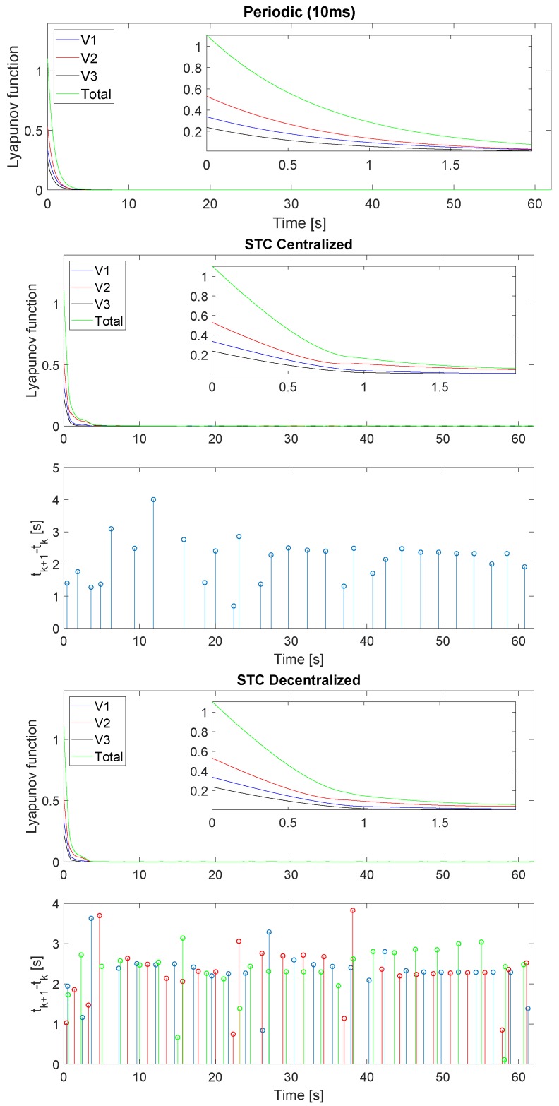
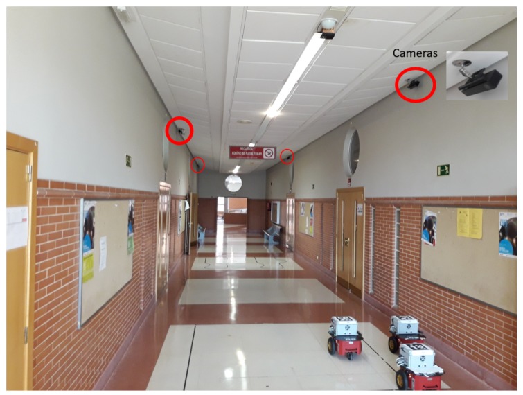
In this paper, we report the design of an aperiodic remote formation controller applied to nonholonomic robots tracking nonlinear, trajectories using an external positioning sensor network. Our main objective is to reduce wireless communication with external sensors and robots while guaranteeing formation stability. Unlike most previous work in the field of aperiodic control, we design a self-triggered controller that only updates the control signal according to the variation of a Lyapunov function, without taking the measurement error into account. The controller is responsible for scheduling measurement requests to the sensor network and for computing and sending control signals to the robots. We design two triggering mechanisms: centralized, taking into account the formation state and decentralized, considering the individual state of each unit. We present a statistical analysis of simulation results, showing that our control solution significantly reduces the need for communication in comparison with periodic implementations, while preserving the desired tracking performance. To validate the proposal, we also perform experimental tests with robots remotely controlled by a mini PC through an IEEE 802.11g wireless network, in which robots pose is detected by a set of camera sensors connected to the same wireless network.

Keywords: formation control; nonlinear trajectory tracking; practical stability; real-time scheduling; remote guidance; self-triggered Lyapunov control.


Conflict of interest statement

The authors declare no conflict of interest.

Figures

Figure 1
Figure 1
(a) main variables describing the trajectory tracking in formation strategy: in blue, the reference poses of each robot Rn (Xrn,Yrn,Θrn), which are generated according the position of a virtual leader robot L (XL,YL,ΘL) in red and in black the current position of each robot, described by Fn (Xn,Yn,Θn); (b) main variables describing trajectory tracking of one robot in the formation, where the robot reference is computed according to the position of the virtual leader: dn is the distance error calculated from the robot point (Xn,Yn) to the reference point (Xrn,Yrn), αn is the orientation error with respect to the target point, eΘn is the orientation error between the desired orientation to follow the trajectory (Θrn) and the orientation of the robot (Θn).
Figure 2
Figure 2
Description of the Theorem 1 triggering condition (16). If the Lyapunov function is greater than V0, the system is updated every time the derivative of the Lyapunov function is non-negative. If the system converges to the invariant set defined by V0, the system is triggered only when the Lyapunov function reaches the threshold V0.
Figure 3
Figure 3
Main variables describing the formation strategy: in blue color the reference poses of each robot Rn (Xrn,Yrn,Θrn), which are generated according the position of the Virtual Leader L (XL,YL,ΘL) in red.
Figure 4
Figure 4
Nonlinear trajectory tracked by the formation of three robotic units. Robot 1 is represented in blue, Robot 2 in red and Robot 3 in black. The route followed by each robot is presented with a continuous line, the reference with a discontinuous line, and every 13 s the punctual position of each of them is shown with a circle and an x, respectively. The top figure represents the periodic implementation, the middle one the STC with centralized triggering (26) and the bottom the STC with decentralized triggering (27).
Figure 5
Figure 5
Linear and angular velocity references and commands of the formation. Robot 1 is represented in top figure, Robot 2 in middle one and Robot 3 in the bottom. The velocity done by each robot is presented in blue for the periodic implementation, in red for the STC with decentralized triggering (27) and in black for the centralized triggering (26). The velocity reference of each unit is presented in green.
Figure 6
Figure 6
Lyapunov function of the formation including a zoom of the first 2 s and inter-execution times for STC startegies. Robot 1 is drawn in blue, Robot 2 in red, Robot 3 in black and the Formation in green. Top figure represents the periodic implementation, the middle one the STC with centralized triggering (26) and the bottom the STC with decentralized triggering (27).
Figure 7
Figure 7
Description of the main elements in our implementation scenario: the remote centre, the robots formation, the camera network and the wireless communication channel. The remote centre carry out the principal tasks: reference trajectory generation of each robot according to the road-following strategy, unscented Kalman filter(UKF) and self-triggered control based on Lyapunov functions for asynchronous request of measurements and actuations on the robots.
Figure 8
Figure 8
Communication protocol between the remote centre, sensor and robot, with the delay compensation strategy.
Figure 9
Figure 9
Picture of the working area with four Kinect 2 camera sensor and the formation of three P3DX robot wirelessly controlled by a miniPC.
Figure 10
Figure 10
The nonlinear, trajectory tracking by the formation of three robotic units. Robot 1 is represented in blue, Robot 2 in red and Robot 3 in black, the route done by each robot is presented with a continuous line, the reference with a discontinuous line, and every 13 s the punctual position of each of them is shown with a circle and an x, respectively. The top figure represents the periodic implementation, the middle one the STC with centralized triggering (26) and the bottom the STC with decentralized triggering (27).
Figure 11
Figure 11
Linear and angular velocity references and commands of the formation. Robot 1 is represented in the top figure, Robot 2 in the middle one and Robot 3 in the bottom. The velocity done by each robot is presented in blue for the periodic implementation, in red for the STC with decentralized triggering (27) and in black for the centralized triggering (26). The velocity reference of each unit is presented in green.
Figure 12
Figure 12
Lyapunov function of the formation and inter-execution times for STC strategies. Robot 1 is represented in blue, Robot 2 in red, Robot 3 in black and the Formation in green. The top figure represents the periodic implementation, the middle one the STC with centralized triggering (26) and the bottom the STC with decentralized triggering (27).

References

    1. Oh K.K., Park M.C., Ahn H.S. A survey of multi-agent formation control. Automatica. 2015;53:424–440. doi: 10.1016/j.automatica.2014.10.022. - DOI
    1. Guinaldo M., Fábregas E., Farias G., Dormido-Canto S., Chaos D., Sánchez J., Dormido S. A Mobile Robots Experimental Environment with Event-Based Wireless Communication. Sensors. 2013;13:9396–9413. doi: 10.3390/s130709396. - DOI - PMC - PubMed
    1. Santos C., Espinosa F., Santiso E., Martínez M., Mazo M. Aperiodic Consensus Control for Tracking Nonlinear Trajectories of a Platoon of Vehicles; Proceedings of the 2015 IEEE 18th International Conference on Intelligent Transportation Systems; Gran Canaria, Spain. 15–18 September 2015; pp. 1983–1988.
    1. Yan Z., Xu D., Chen T., Zhang W., Liu Y. Leader–Follower Formation Control of UUVs with Model Uncertainties, Current Disturbances, and Unstable Communication. Sensors. 2018;18:662. doi: 10.3390/s18020662. - DOI - PMC - PubMed
    1. Dong X., Yu B., Shi Z., Zhong Y. Time-Varying Formation Control for Unmanned Aerial Vehicles: Theories and Applications. IEEE Trans. Control Syst. Technol. 2015;23:340–348. doi: 10.1109/TCST.2014.2314460. - DOI

LinkOut - more resources