

doi: 10.1098/rsif.2019.0244.
Epub 2019 Jun 19.
Simple mechanics of protein machines
Affiliations
- PMID: 31213170
- PMCID: PMC6597773
- DOI: 10.1098/rsif.2019.0244
Item in Clipboard
Simple mechanics of protein machines
J R Soc Interface.
.
Abstract
While belonging to the nanoscale, protein machines are so complex that tracing even a small fraction of their cycle requires weeks of calculations on supercomputers. Surprisingly, many aspects of their operation can be however already reproduced by using very simple mechanical models of elastic networks. The analysis suggests that, similar to other self-organized complex systems, functional collective dynamics in such proteins is effectively reduced to a low-dimensional attractive manifold.
Keywords: allosteric effects; complex systems; elastic networks; mechanochemical motions in enzymes; molecular motors; self-organization.
Conflict of interest statement
We declare we have no competing interests.
Figures
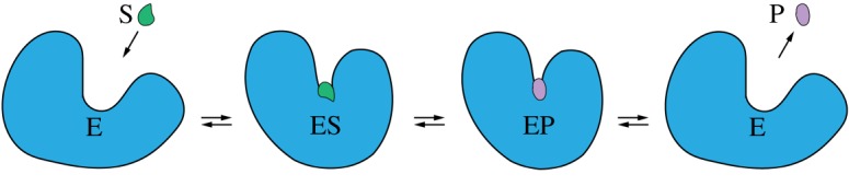
A sketch of mechanochemical motions accompanying the catalytic turnover cycle of an enzyme. (Online version in colour.)
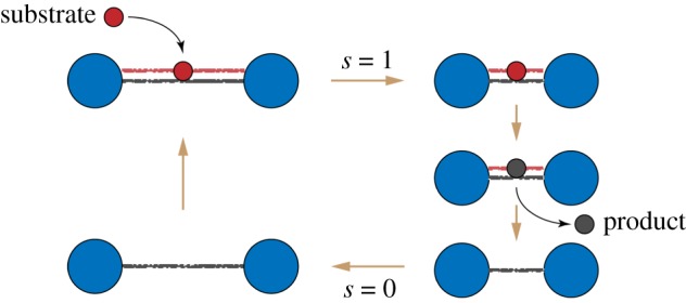
The cycle of an active dimer. A substrate (red) binds and induces shortening of the dimer. Then, the substrate is converted to a product (black), and the product is released. Finally, the dimer returns to its original shape. (Online version in colour.)
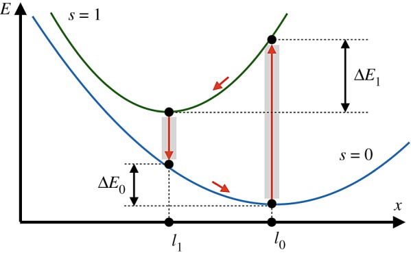
Energy diagram of the active dimer. Two branches of the dependence of elastic energy E on distance x between the beads for configurations with (s = 1) and without (s = 0) a ligand are shown. Transitions between the branches occur at x = l0 and x = l1; they are followed by relaxation to new equilibrium states. Within each turnover cycle, energy ΔE0 + ΔE1 is dissipated in mechanical motions and the same energy is externally supplied through the ligand. (Online version in colour.)
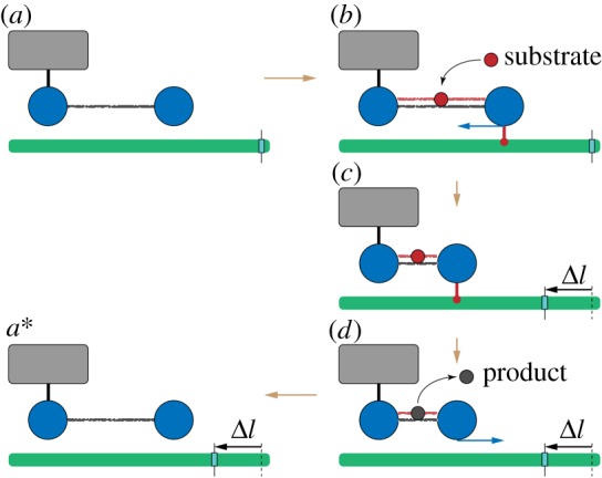
A ratchet motor. The left bead of the dimer is immobilized (schematically shown by a link to the grey box). The filament (green) is mobile and can slide. (a) Initially, the dimer is in the expanded state without a ligand. (b) When a substrate arrives, the right bead of the dimer forms a connection to the filament and holds it. (c) As the dimer contracts, it moves the sliding filament to the left. (d) Once the product is formed and immediately released, the connection between the dimer and the filament disappears, and the dimer freely expands. (a*) After one machine cycle, the dimer returns to its initial configuration, but the filament becomes displaced to the left by the distance Δl = l0 − l1. To visualize the displacement, a mark is attached to the filament. See also the electronic supplementary material, video S1. (Online version in colour.)
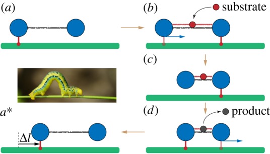
An inchworm translocation motor. The filament (green) is immobile and the dimer machine can actively translocate itself along it. (a) Initially, the left bead of the dimer is connected to the filament and holds it. (b) When a substrate arrives, a connection between the right bead and the filament is established and then the left bead gets disconnected. (c) The dimer contracts, bringing the left bead closer to the immobile right bead. (d) When a product is formed and instantaneously released, the left bead re-establishes a connection to the filament and becomes immobile, whereas the right bead is disconnected. (a*) The free dimer expands and reaches its initial conformation. After one cycle, its location on the filament is shifted by the distance Δl = l0 − l1. The inset shows an animal inchworm. See also the electronic supplementary material, video S2. (Online version in colour.)
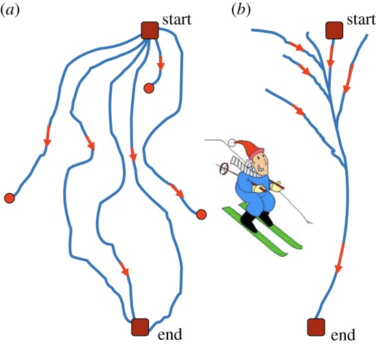
A sketch of downhill skiing over (a) a ragged slope and (b) a slope with a narrow valley. (Online version in colour.)
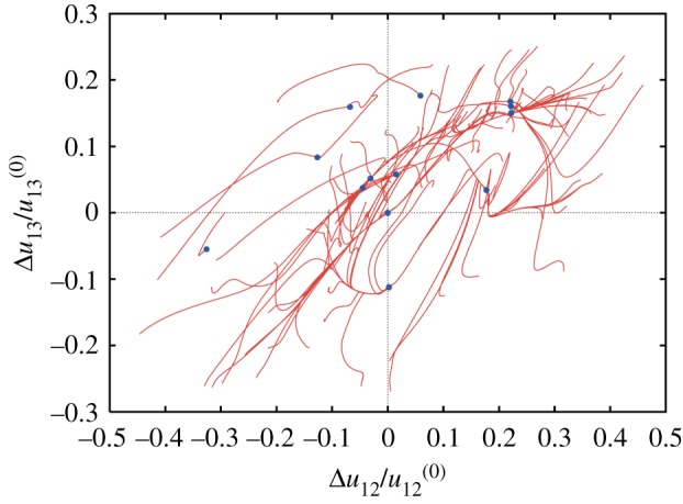
Conformational relaxation in a random elastic network. Each of the 100 displayed relaxation trajectories starts from a different initial conformation; blue dots indicate final states. Projection on the plane of normalized deviations of distances between three randomly chosen labels from their respective values in the equilibrium reference state. The reference state corresponds therefore to the origin of coordinates. Adapted from [20]. (Online version in colour.)
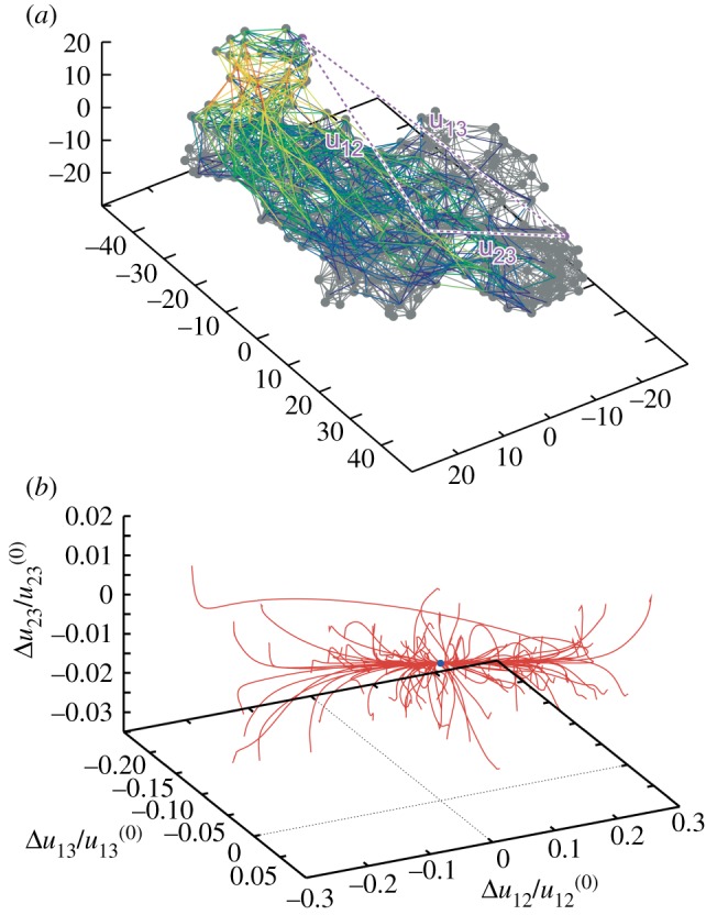
Elastic network of a single β-subunit of the molecular motor F1-ATPase (a) and the set of relaxation trajectories for this network (b). Links in the elastic network are coloured according to their deformations in the slowest normal mode (with red for the most strong and blue for the most weak deformations). Each of the 100 trajectories starts from a different initial network conformation. Trajectories are displayed in the space of relative distance changes between labels (1,2,3) indicated in the elastic network. The equilibrium state corresponds to the origin of coordinates. Adapted from [20]. (Online version in colour.)
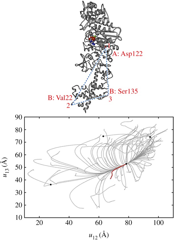
Conformational relaxation in myosin V. Here, 100 relaxation trajectories starting from different initial network conformations are plotted in the plane of distances between the labels (1,2,3) indicated above. Black dots mark the equilibrium and the metastable states reached. The ATP-bound equilibrium structure is taken as a reference state. The red trajectory corresponds to the conformational transition upon ATP binding. Adapted from [28]. (Online version in colour.)
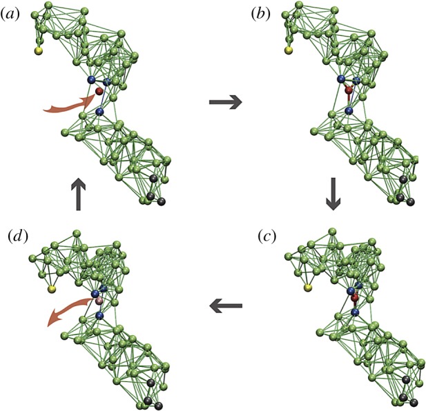
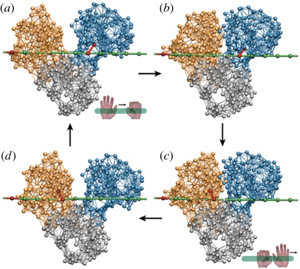
The cycle of a model elastic network machine [20]. (a) Initially, the machine is in its equilibrium state. (b) A substrate (red) establishes elastic links to three beads (blue) in the hinge region between the two domains. (c) The machine changes its conformation to the new equilibrium state. (d) In this state, a reaction converting the substrate into product takes place and the product is instantaneously released. After that, the machine returns to its original conformation, completing the cycle. When the machine is used to construct a motor, three black beads in the lower domain are immobilized and the yellow bead in the upper domain interacts with the filament. Reproduced from [35]. See also the electronic supplementary material, video S3. (Online version in colour.)
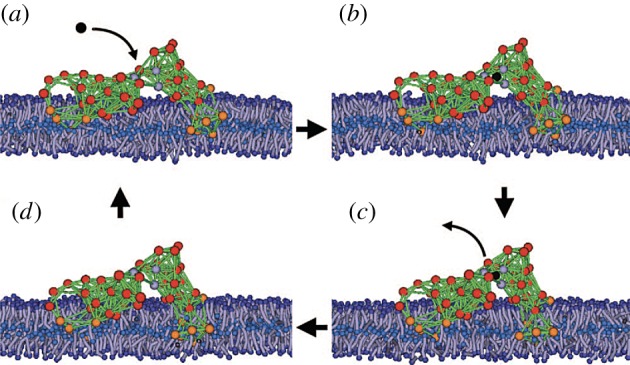
The model protein machine in a biological membrane. The lipids are modelled as short polymer strings. Orange beads are hydrophobic and red beads are hydrophilic. The solvent is included into the simulations, but its particles are not displayed. Adapted from [38]. See also the electronic supplementary material, video S4. (Online version in colour.)
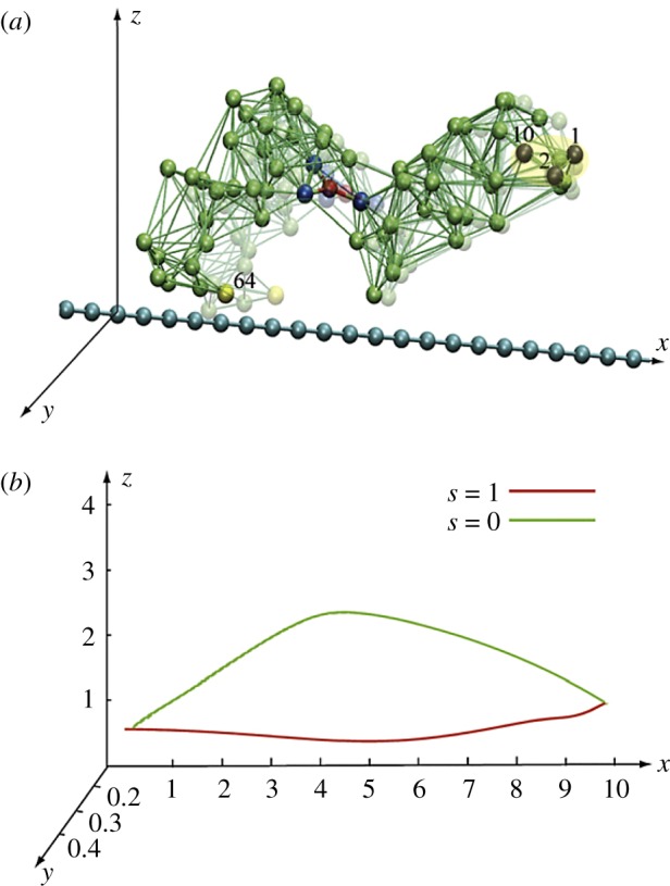
Construction of a model ratchet motor. (a) Beads 1, 2 and 10 are fixed, immobilizing one domain. Bead 64 can interact with the force centres (blue beads) on the filament. The filament can only slide along its direction. (b) The trajectory of bead 64 within one cycle. In the ligand-bound state s = 1, the bead comes close to the filament, establishes interactions, and moves it. In the second half of the cycle (s = 0), this bead is separated from the filament and moves back without holding it. Thus, the filament becomes progressively translocated after each cycle. Adapted from [38]. See also the electronic supplementary material, video S5. (Online version in colour.)
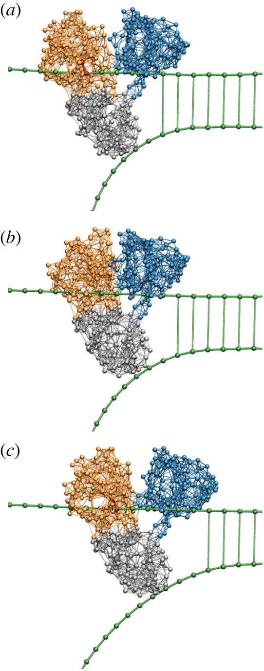
The inchworm translocation cycle of HCV helicase. Following ATP binding, the left motor domain (orange) moves towards the right motor domain (blue), so that the protein conformation is changed from (a) the open to (b) the closed one. In the closed conformation, hydrolysis occurs and its products are released (c), inducing the return (d) to the initial open conformation. Within the cycle, interactions between the motor domains and the DNA strand (green) are switched. When ATP binds, a link (red) between the right domain and the strand is established, so that this domain holds the DNA. After the hydrolysis, the reconnection occurs (c) and now the left domain grasps the DNA. As a result, the motor translocates itself by one DNA base in the right direction after each cycle. Adapted from [29]. See also the electronic supplementary material, video S6. (Online version in colour.)
The operation of HCV helicase. Forced by translocation of the two motor domains along the upper strand, the third domain (grey) is drawn as a wedge between the two DNA strands and thus mechanically separates them. Three consequent snapshots (a,b,c) from a structurally resolved coarse-grained simulation [29] are displayed. See also the electronic supplementary material, video S7. (Online version in colour.)
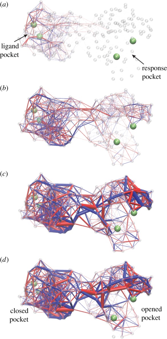
Deformation spreading through a designed elastic network with asymmetric cooperativity. Four consequent snapshots are displayed. Upon ligand binding, elastic links around the pocket in the left domain become strained (a). Later on, the deformation propagates into the interface between the two domains (b,c). Eventually, the links around the pocket in the right domain get strained (c,d). Thus, contraction of the ligand pocket in the left domain leads to opening of the pocket in the right domain, i.e. to an allosteric effect. Bond thickness visualizes the strain magnitude of the respective elastic link. The colour indicates whether a link is stretched (blue) or compressed (red). Contracting forces were applied to two beads (green) in the ligand pocket. The allosteric effect was quantified by measuring the distance between two beads (green) in the response pocket. Adapted from [33]. See also the electronic supplementary material, video S8. (Online version in colour.)
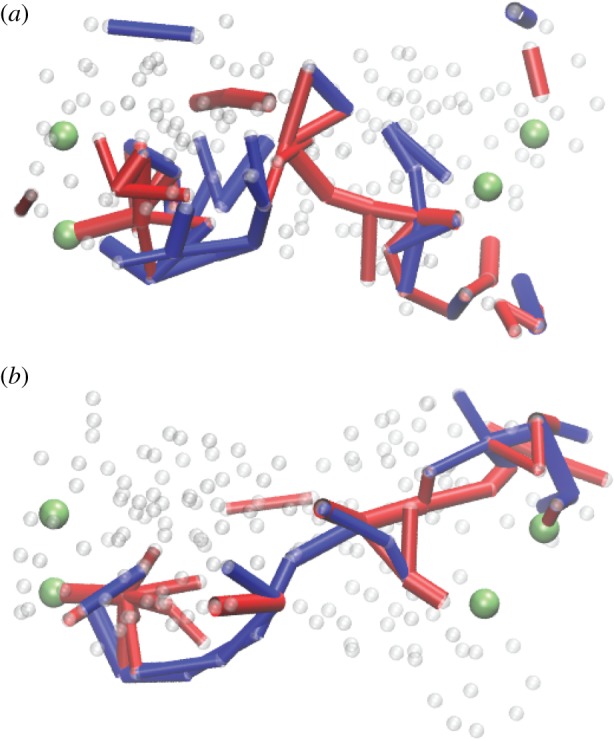
Communication pathways in designed networks with (a) symmetric and (b) asymmetric cooperativity. The network in (b) is the same as in figure 15. Here, only the links whose maximum absolute deformation during strain propagation has exceeded a threshold are retained. The same colour coding as in figure 15. Adapted from [33]. (Online version in colour.)
References
Publication types
MeSH terms
Substances
LinkOut - more resources
Full Text Sources